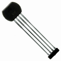
ATS612LSB Allegro Microsystems Inc, ATS612LSB Datasheet - Page 13

ATS612LSB
Manufacturer Part Number
ATS612LSB
Description
IC SENSOR GEAR TOOTH 4LEAD
Manufacturer
Allegro Microsystems Inc
Type
Special Purposer
Datasheet
1.ATS612LSB.pdf
(17 pages)
Specifications of ATS612LSB
Sensing Range
*
Voltage - Supply
3.6 V ~ 24 V
Current - Supply
15mA
Current - Output (max)
55mA
Output Type
Digital, Open Collector
Features
Gear Tooth Type
Operating Temperature
-40°C ~ 150°C
Package / Case
4-SIP
Lead Free Status / RoHS Status
Contains lead / RoHS non-compliant
Available stocks
Company
Part Number
Manufacturer
Quantity
Price
Company:
Part Number:
ATS612LSB
Manufacturer:
ATMEL
Quantity:
201
Recommended Evaluation Technique. The self-
calibrating feature of the ATS612LSB requires that a
special evaluation technique be used to measure its high-
accuracy performance capabilities. Installation inaccura-
cies are calibrated out at power on only; hence, it is
extremely important that the device be re-powered at each
air gap when gathering timing accuracy data.
Self-Calibrating Functions. The ATS612LSB is de-
signed to minimize performance variation caused by the
large air gap variations resulting from installation by self-
calibrating at power-on. This function should be tested
using the following procedure.
1. Set the air gap to the desired value.
2. Power down and then power on the device.
3. Rotate the target at the desired speed.
4. Wait for calibration to complete (64 output pulses to
5. Monitor output for correct switching and measure
6. Repeat the above for multiple air gaps within the
7. This can be repeated over the entire operating tem-
Measurement of the effect of changing air gap after power
on:
1. Set the air gap to the desired value (nominal, for
2. Change the air gap by ± 0.25 mm. Do not re-power
12
ATS612LSB
DYNAMIC, SELF-CALIBRATING, PEAK-DETECTING,
DIFFERENTIAL HALL-EFFECT GEAR-TOOTH SENSOR IC
occur).
accuracy.
operating range of the device.
perature range.
example). Rotate the target at the desired speed.
Apply power to the package. Wait for 64 output pulses
to occur. Monitor output for correct switching and
measure accuracy.
device. Monitor the output for correct switching and
measure accuracy.
APPLICATIONS INFORMATION
115 Northeast Cutoff, Box 15036
Worcester, Massachusetts 01615-0036 (508) 853-5000
Gear Diameter and Pitch. Signal frequency is a direct
function of gear pitch and rotational speed (RPM). The
width of the magnetic signal in degrees and, hence, the
signal slope created by the tooth is directly proportional to
the circumference of the gear (πD o ). Smaller diameters
limit the low-speed operation due to the slower rate of
change of the magnetic signal per degree of gear rotation
(here the limitation is the droop of the capacitor versus the
signal change). Larger diameters limit high-speed opera-
tion due to the higher rate of change of magnetic signal
per degree of rotation (here the limitation is the maximum
charge rate of the capacitor versus the rate of signal
change). These devices are optimized for a 50mm gear
diameter (signal not limited by tooth width), 0.22 µF
capacitor, and speeds of 10 RPM to 8000 RPM. For very
large diameter gears (diameter >200 mm), the devices
must be configured with a lower value capacitor, but not
less than 0.1 µF. This allows for a range of 5:1 in gear
diameters.
Air Gap and Tooth Geometry. Operating specifications
are impacted by tooth width (T), valley width (p
depth (h
target can be a gear or a specially cut shaft-mounted tone
wheel made of stamped ferrous metal. In general, the
following gear or target guidelines must be followed to
achieve greater than 2mm air gap from the face of unit:
reduction of air gap and a deterioration in timing accuracy.
Tooth width, T .............................. >2 mm
Valley width, p
(Whole) depth, h
Gear material ............................... low-carbon steel
Gear face width (thickness), F ..... >3 mm
Deviation from these guidelines will result in a
t
), gear material, and gear face thickness (F). The
c
- T ...................... >2 mm
t
......................... >3 mm
c
- T) and


