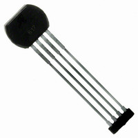
ATS612LSB Allegro Microsystems Inc, ATS612LSB Datasheet - Page 12

ATS612LSB
Manufacturer Part Number
ATS612LSB
Description
IC SENSOR GEAR TOOTH 4LEAD
Manufacturer
Allegro Microsystems Inc
Type
Special Purposer
Datasheet
1.ATS612LSB.pdf
(17 pages)
Specifications of ATS612LSB
Sensing Range
*
Voltage - Supply
3.6 V ~ 24 V
Current - Supply
15mA
Current - Output (max)
55mA
Output Type
Digital, Open Collector
Features
Gear Tooth Type
Operating Temperature
-40°C ~ 150°C
Package / Case
4-SIP
Lead Free Status / RoHS Status
Contains lead / RoHS non-compliant
Available stocks
Company
Part Number
Manufacturer
Quantity
Price
Company:
Part Number:
ATS612LSB
Manufacturer:
ATMEL
Quantity:
201
become qualified, except for the destructive ESD tests, no failures are permitted.
obtained by measuring the voltage at pin 3 (the capacitor
pin) while the device is running. The peak and valley hold
voltage will represent the peak-to-peak value of the signal.
More accurate measurements can be taken by connecting
an extremely small capacitor (0.05 µF) from pin 3 to
ground. After the device is powered up and has switched
at least 64 times, a 1 kΩ bleed-off resistor should be
installed in parallel with the capacitor without powering
down the device. If the gear is then rotated at an ex-
tremely low speed, an analog representation of the gain-
Qualification Test
T
Bias Life
B
S (
A
H
(Bake) Storage Life
Temperature Cycle
ESD,
H
e
a i
u
g i
u
www.allegromicro.com
u
m
o t
m
s
h
g r
p
c
T -
a
i L
All Allegro devices are subjected to stringent qualification requirements prior to being released to production. To
An analog map of the magnetic signal can be
e
e
a l
n
e f
e
a r
O
v
B
m
, e
u t
p
o
p
r e
d
e r
U
e
y
t a
a r
n
H
M
b
n i
u t
u
a i
o
g
e r
m
d
s
L
l e
e
d i
f i
d
y t i
) e
DIFFERENTIAL HALL-EFFECT GEAR-TOOTH SENSOR IC
T
Test Conditions
J
T
J
T
J
T
J
T
J
T
JESD22-A104
CDF-AEC-Q100-002
E
E
E
E
E
e
A
A
A
A
A
t s
S
S
S
S
S
= 85°
= 150°C, T
= 175°C, T
= 121°C, 15 psig
= 170°C
D
D
D
D
D
M
2
2
2
2
2
DYNAMIC, SELF-CALIBRATING, PEAK-DETECTING,
2
2
2
2
2
e
A -
A -
A -
A -
A -
h t
, C
CRITERIA FOR DEVICE QUALIFICATION
GEAR/TARGET SYSTEM EVALUATION*
o
1
1
1
1
1
R
0
0
0
0
0
d
, 1
, 8
, 8
, 2
, 3
H
a
J
J
n
=
= 165°C
= 190°C
d
8
5
%
Test Length
1000 cycles
adjusted signal can be measured at pin 3. Note that the
device should be re-powered at each air gap and the
above procedure repeated for accurate measurements. In
both cases, the analog signal may be compared to the
typical hysteresis of the device and device performance
can be estimated.
* In application, the terms “gear” and “target” are often
interchanged. However, “gear” is preferred when motion
is transferred.
1
1
1
Pre/Post
R
1
0
0
9
0
e
6
0
0
6
0
8
a
0
0
0
h
d
h
n i
h
h
s r
h
s r
s r
s r
s r
g
S
Per Lot
a
3 per
m
e t
7
7
7
7
7
77
7
7
7
7
7
p
t s
e l
s
Comments
D
m
-55°C to +150°C
Test to failure
P
All other pins > 3 kV
n i
e
i n i
v
ATS612LSB
3
c i
m
e
>
u
m
b
1
a i
5 .
p
s
o
k
e
w
V
d
r e
f
r o
11


