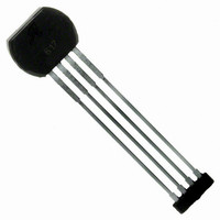
ATS612LSB Allegro Microsystems Inc, ATS612LSB Datasheet - Page 10

ATS612LSB
Manufacturer Part Number
ATS612LSB
Description
IC SENSOR GEAR TOOTH 4LEAD
Manufacturer
Allegro Microsystems Inc
Type
Special Purposer
Datasheet
1.ATS612LSB.pdf
(17 pages)
Specifications of ATS612LSB
Sensing Range
*
Voltage - Supply
3.6 V ~ 24 V
Current - Supply
15mA
Current - Output (max)
55mA
Output Type
Digital, Open Collector
Features
Gear Tooth Type
Operating Temperature
-40°C ~ 150°C
Package / Case
4-SIP
Lead Free Status / RoHS Status
Contains lead / RoHS non-compliant
Available stocks
Company
Part Number
Manufacturer
Quantity
Price
Company:
Part Number:
ATS612LSB
Manufacturer:
ATMEL
Quantity:
201
• Tilted or off-center installation. Traditional differen-
• Large operating air gaps. Operating air gaps greater
• Immunity to magnetic overshoot. The air gap-
• Response to surface defects in the target. The gain-
• Immunity to vibration and backlash. The gain-adjust
• Immunity to gear run out. The differential element
Differential vs. Single-Element Design . The differential
Hall-element configuration is superior in most applications
to the classical single-element gear-tooth sensor. As
shown in the flux maps on this page, the
single-element configuration commonly used (Hall-effect
sensor mounted on the face of a simple permanent
magnet) requires the detection of a small signal (often
<100G) that is superimposed on a large back-biased field,
often 1500G to 3500G. For most gear/target configura-
tions, the back-biased field values change due to concen-
tration effects, resulting in a varying baseline with air gap,
with valley widths, with eccentricities, and with vibration.
The differential configuration cancels the effects of the
back-biased field and avoids many of the issues presented
by the single Hall element.
NOTE — 10 G = 1 mT, exactly.
www.allegromicro.com
tial sensors will switch incorrectly due to baseline
changes versus air gap caused by tilted or off center
installation. The peak detector circuitry references the
switch point from the peak and is immune to this failure
mode. There may be a timing accuracy shift caused by
this condition.
than 2.5 mm are easily achievable (dependent on target
dimensions, material, and speed) with this device due
to the sensitive switch points after start up.
independent hysteresis minimizes the impact of over-
shoot on the switching of device output.
adjust circuitry reduces the effect of minor gear anoma-
lies that would normally cause false switching.
circuitry keeps the hysteresis of the device roughly
proportional to the peak to peak signal. This allows the
device to have good immunity to vibration even when
operating at close air gaps.
configuration eliminates the base line variations caused
by gear run out.
DIFFERENTIAL HALL-EFFECT GEAR-TOOTH SENSOR IC
DYNAMIC, SELF-CALIBRATING, PEAK-DETECTING,
DEVICE DESCRIPTION — Continued
-1500
-1000
-5000
1500
1000
-2000
-2500
-3000
-3500
-4000
-4500
-500
500
0
showing the impact of varying valley widths
0
0
Differential flux maps vs. air gaps
ANGLE OF TARGET ROTATION IN DEGREES
ANGLE OF TARGET ROTATION IN DEGREES
10
10
AIR GAP = 0.5 mm
AIR GAP = 1.0 mm
Single-element flux maps
AIR GAP = 2.5 mm
AIR GAP = 2.0 mm
AIR GAP = 1.5 mm
20
20
TARGET
TARGET
30
30
ATS612LSB
40
40
AIR GAP = 0.5 mm
AIR GAP = 2.5 mm
AIR GAP = 2.0 mm
AIR GAP = 1.5 mm
AIR GAP = 1.0 mm
T
T
A
A
50
50
= 25°C
= 25°C
Dwg. GH-061-1
Dwg. GH-061
60
60
9


