XTPAXLSA EATON CUTLER HAMMER, XTPAXLSA Datasheet - Page 246
XTPAXLSA
Manufacturer Part Number
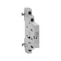
XTPAXLSA
Description
Line-Side Adapter
Manufacturer
EATON CUTLER HAMMER
Datasheet
1.XTCE007B10A.pdf
(312 pages)
Specifications of XTPAXLSA
For Use With
Eaton Cutler-Hammer XT Series Frame B Manual Motor Protectors
Lead Free Status / RoHS Status
Lead free / RoHS Compliant


34-246
34
Auxiliary Contacts
Table 34-284. Auxiliary Contact Availability — A – F Frames
Figure 34-153. Connecting Diagram — A – F Frames
Table 34-285. Auxiliary Contact Availability — F-Frame 140 mm
Note:
■
■
■
■
Front Mounted (Maximum Auxiliaries per Contactor/Starter)
Contactor/Starter Size
A-Frame
27 mm
1
1
—
—
—
1
Auxiliary Contacts per Non-reversing and Reversing Contactor or Starter
Max. Contact
2
2
6
2
6
2
2
2
3
Side Mounted: Maximum (10) total circuits.
Front Mounted: Maximum (6) total circuits.
Maximum 4 auxiliaries per side (base + 3 side mounted).
EMASA/B_ have been superseded by the above Catalog Numbers.
EMA13
Other combinations: “Single, dual, single”; “Dual, single, dual”; “Dual, logic level, dual”.
For reversers, multiply quantities by two.
Form C Contacts.
For reversers, multiply quantities by two.
NO
IEC Contactors & Starters
IT. Electro-Mechanical
Accessories
3
4
Type
1NO
1NO-1NC
1NO
1NO
Logic Level
1NC
1NC
Logic Level
1NO-1NC
1NO-1NC
Logic Level
1NO-1NC
Logic Level
B-Frame
45 mm
3
3
2
2
2
2
NC
2
1
EMA14
C-Frame
54 mm
3
3
2
2
2
3
Description
Base auxiliary (max. 1 per side)
Base auxiliary (max. 1 per side)
C320KGS41 or C320KGS42 required
(max. 3 Add-on auxiliaries per side)
C320KGS41 or C320KGS42 required
(max. 1 Add-on auxiliary per side)
C320KGS41 or C320KGS42 required
(max. 2 Add-on auxiliaries per side)
C320KGS41 or C320KGS42 required
(max. 1 Add-on auxiliary per side)
C320KGS41 or C320KGS42 required
(max. 1 Add-on auxiliary per side)
C320KGS41 or C320KGS42 required
(max. 1 Add-on auxiliary per side)
Front Mounted Only
NO
13
14
EMA15
D-Frame
76 mm
3
3
3
3
3
3
21
NC
22
E-Frame
105 mm
3
3
3
3
3
3
NO
14
13
EMA16
Auxiliary Contacts are available for
mounting on IT. Electro-Mechanical
Contactors and Starters. The various
choices available for non-reversing
models are shown in Tables 34-284
and 34-285, and their ratings in Tables
34-286 – 34-288. For reversing models,
the number of auxiliaries indicated is
for each of the contactors/starters in
the assembly.
For more information visit: www.eaton.com
F-Frame
140 mm
—
—
—
—
—
3
23
NO
24
NC
12
11
Catalog
Number
C320KGS41
C320KGS42
C320KGS20
C320KGS20L
C320KGS21
C320KGS21L
C320KGS22
C320KGS22L
EMA70
Contact
Type
1NO
1NC
1NO-1NC
2NO
2NC
Logic Level
1NO-1NC
EMA17
21
NC
22
Catalog
Number
EMA13
EMA14
EMA15
EMA16
EMA17
EMA70
NO
4
1
Common
Price
U.S. $
EMA70
Price
U.S. $
2
NC
1
Table 34-286. IEC Ratings
Table 34-287. NEMA A600 Ratings
Table 34-288. NEMA P300 Ratings
Table 34-289. EMA70 Auxiliary Contact
Starter Network Adapter Product
(SNAP)
The Starter Network Adapter Product
(SNAP) is a front-mount device that
serves as a single DeviceNet node, pro-
viding communication capability, control
and monitoring to Eaton’s Cutler-Ham-
mer Intelligent Technologies (IT.) Electro-
mechanical Starters (B – F Frames) as
well as the IT. S75X SoftStart.
When HAND-OFF-AUTO is required,
the HOA option will allow for the con-
nection of hard wired operators. This
option allows for Hand Control even if
the DSNAP is not connected.
For more information and pricing, see
Tab 50.
Discount Symbol . . . . . . . . . . . . . . . . . . . . . . . . 1CD1
DC-13
U
Voltage
125
250
Current
Make and
Interrupting
Break
Continuous
Thermal
Current
Make and
Interrupting
Break
Continuous
Thermal
DC-12
Ue
30
24
48
e
Ie
.1
l
Amps.
5
2.5
1.1
e
.55
Cat. No. D77B-DSNAP-X1
with 54 mm IT. Starter
AC Voltage
120
60
10
10
DC Voltage
125
1.1
1.1
5
5
6
AC-15
U
Voltage
120
240
440
AC-12
Ue
250
48
e
240
30
10
10
3
480
15
10
10
250
5
5
CA08102001E
1.5
.55
.55
March 2009
Ie
.1
l
Amps.
8
6
4
2
e
600
12
10
10
1.2
Related parts for XTPAXLSA
Image
Part Number
Description
Manufacturer
Datasheet
Request
R

Part Number:
Description:
PROGRAMMABLE LOGIC CONTROLLER
Manufacturer:
EATON CUTLER HAMMER
Part Number:
Description:
Pm Power Pro 3000/5000 A-B Accel/On Interface
Manufacturer:
EATON CUTLER HAMMER
Part Number:
Description:
Handle Tie Bar For (2) - 1 Pole Type BR Breakers
Manufacturer:
EATON CUTLER HAMMER
Part Number:
Description:
Type CH Breaker 150A/2 Pole 120/240V 10K
Manufacturer:
EATON CUTLER HAMMER
Part Number:
Description:
Tenant Branch Breaker 125A/3 Pole 120/240V 42K
Manufacturer:
EATON CUTLER HAMMER
Part Number:
Description:
Type CL Breaker 25A/1Pole 120/240V 10K-Classified 1" Ckt Bkr
Manufacturer:
EATON CUTLER HAMMER
Part Number:
Description:
FD BREAKER 1P 80 AMP WITH LOAD ONLY TERMINALS
Manufacturer:
EATON CUTLER HAMMER
Part Number:
Description:
GD 2 POLE BREAKER, 25 AMP, SINGLE PACKED
Manufacturer:
EATON CUTLER HAMMER
Part Number:
Description:
Handle Tie Bar For (2) - 1 Pole Type BR Breakers
Manufacturer:
EATON CUTLER HAMMER
Part Number:
Description:
Type CL Breaker 25A/1Pole 120/240V 10K-Classified 1" Ckt Bkr
Manufacturer:
EATON CUTLER HAMMER