XTPAXLSA EATON CUTLER HAMMER, XTPAXLSA Datasheet - Page 241
XTPAXLSA
Manufacturer Part Number
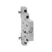
XTPAXLSA
Description
Line-Side Adapter
Manufacturer
EATON CUTLER HAMMER
Datasheet
1.XTCE007B10A.pdf
(312 pages)
Specifications of XTPAXLSA
For Use With
Eaton Cutler-Hammer XT Series Frame B Manual Motor Protectors
Lead Free Status / RoHS Status
Lead free / RoHS Compliant


March 2009
Table 34-278. Specifications (Continued)
Finger Protection
Terminals L1, L2, L3/T1, T2, T3
Operation Performance
Control Terminals
Temperature
CA08102001E
Description
Front
At Terminals
At Terminals with
max. size wire
installed
1 Wire per Terminal
(stranded or solid)
2 Wires per Terminal
(stranded or solid)
Strip Length
Torque (max.)
Driver
Coil Voltage (nominal) 24V DC
Coil Operating
Voltage Range (VDC)
(- and +)
1 Wire per Terminal
(- and +)
2 Wires per Terminal
(P, F, R, 1, 2, 3)
1 Wire per Terminal
(P, F, R, 1, 2, 3)
2 Wires per Terminal
Torque (max.)
Strip Length
Driver (Flat)
Operating
Storage
Flat
Hex Key
Use Class B 75°C copper wire only (or 90°C
copper wire sized for 75°C operation per NEC).
Not applicable to starter T1, T2, T3. One wire per terminal.
27 mm Non-reversing Starter —
• (- and +) 14 AWG (1.5 mm
• P, F, 1, A: 1 wire per terminal only,
• Torque: 2.25 lb-in (.25 Nm)
• Driver: .09 in (2.5 mm)
Consult factory for higher ratings.
22 – 14 AWG (0.5 – 1.5 mm
A-Frame
27 mm
IP20
IP20
IP20
16 – 12 AWG
(1.5 – 2.5 mm
16 – 12 AWG
(1.5 – 2.5 mm
.32" (8 mm)
18 lb-in (2.0
Nm)
PZ1 or 3/16"
—
20 – 28
14 – 12 AWG
(1.5 – 2.5 mm
14 AWG
(1.5 mm
22 – 12 AWG
(0.5 – 2.5 mm
18 – 14 AWG
(0.75 – 1.5 mm
4.5 lb-in (.5 Nm) 4.5 lb-in (.5 Nm)
.25 (7 mm)
.13 (3.5 mm)
-40° to +149°F
(-40° to +65°C)
-58° to +176°F
(-50° to +80°C)
2
2
) only
2
)
)
2
2
2
2
)
)
)
)
2
)
IP20
B-Frame
45 mm
IP20
IP10
14 – 8 AWG
(1.5 – 10 mm
14 – 10 AWG
(1.5 – 4 mm
.45" (11 mm)
20 lb-in (2.2 Nm) for
14 – 10 AWG
(1.5 – 6 mm
25 lb-in (2.8 Nm) for
8 AWG (10 mm
—
2.5 mm
24V DC
20 – 28
14 – 12 AWG
(1.5 – 2.5 mm
14 AWG
(1.5 mm
22 – 12 AWG
(0.5 – 2.5 mm
18 – 14 AWG
(0.75 – 1.5 mm
.25 (7 mm)
.13 (3.5 mm)
-40° to +149°F
(-40° to +65°C)
-58° to +176°F
(-50° to +80°C)
2
)
2
2
)
);
2
2
2
)
For more information visit: www.eaton.com
)
)
2
2
)
)
IEC Contactors & Starters
IT. Electro-Mechanical
Technical Data and Specifications
C-Frame
54 mm
IP20
IP10
IP10
14 – 4 AWG
(1.5 – 16 mm
14 – 6 AWG
(1.5 – 16 mm
.5" (12 mm)
35 lb-in (4.0 Nm) for
14 – 10 AWG (1.5 – 6
mm
40 lb-in (4.5 Nm) for
8 AWG (10 mm
45 lb-in (5.0 Nm) for
6 – 4 AWG (16 mm
—
3 mm
24V DC
20 – 28
14 – 12 AWG
(1.5 – 2.5 mm
14 AWG
(1.5 mm
22 – 12 AWG
(0.5 – 2.5 mm
18 – 14 AWG
(0.75 – 1.5 mm
4.5 lb-in (.5 Nm)
.25 (7 mm)
.13 (3.5 mm)
-40° to +149°F
(-40° to +65°C)
-58° to +176°F
(-50° to +80°C)
2
);
2
)
2
2
2
2
)
)
)
)
2
2
)
);
2
)
D-Frame
76 mm
IP20
IP00
IP10
14 – 1 AWG
(1.5 – 35 mm
14 – 2 AWG
(1.5 – 25 mm
.7" (18 mm)
45 lb-in (5.0 Nm) for Single
14 – 8 AWG (1.5 – 10 mm
100 lb-in (11 Nm) for Single
6 – 1 AWG (16 – 35 mm
and Dual Wire Combina-
tions
—
4 mm [5/32"]
24V DC
20 – 28
14 – 12 AWG
(1.5 – 2.5 mm
14 AWG
(1.5 mm
22 – 12 AWG
(0.5 – 2.5 mm
18 – 14 AWG
(0.75 – 1.5 mm
4.5 lb-in (.5 Nm)
.25 (7 mm)
.13 (3.5 mm)
-40° to +149°F
(-40° to +65°C)
-58° to +176°F
(-50° to +80°C)
2
)
2
2
2
2
)
)
)
)
2
)
2
)
2
);
E-Frame
105 mm
IP20
IP00
IP00
6 – 250 MCM
(16 – 120 mm
6 – 3/0 AWG
(16 – 70 mm
.8" (21 mm)
250 lb-in
(28 Nm)
—
8 mm [5/16"]
24V DC
20 – 28
14 – 12 AWG
(1.5 – 2.5 mm
14 AWG
(1.5 mm
22 – 12 AWG
(0.5 – 2.5 mm
18 – 14 AWG
(0.75 – 1.5 mm
4.5 lb-in (.5 Nm) 4.5 lb-in (.5 Nm)
.25 (7 mm)
.13 (3.5 mm)
-40° to +149°F
(-40° to +65°C)
-58° to +176°F
(-50° to +80°C)
2
)
2
2
)
2
2
)
)
)
2
)
F-Frame
140 mm
IP00
IP00
IP00
4 – 750 MCM
(25 – 420 mm
1/0 – 300 MCM
(50 – 150 mm
1.5" (40 mm)
550 lb-in
(62 Nm)
—
8 mm [5/16"]
24V DC
20 – 28
14 – 12 AWG
(1.5 – 2.5 mm
14 AWG
(1.5 mm
22 – 12 AWG
(0.5 – 2.5 mm
18 – 14 AWG
(0.75 – 1.5 mm
.25 (7 mm)
.13 (3.5 mm)
-40° to +149°F
(-40° to +65°C)
-58° to +176°F
(-50° to +80°C)
2
)
34-241
2
2
2
2
)
)
)
)
2
)
34
Related parts for XTPAXLSA
Image
Part Number
Description
Manufacturer
Datasheet
Request
R

Part Number:
Description:
PROGRAMMABLE LOGIC CONTROLLER
Manufacturer:
EATON CUTLER HAMMER
Part Number:
Description:
Pm Power Pro 3000/5000 A-B Accel/On Interface
Manufacturer:
EATON CUTLER HAMMER
Part Number:
Description:
Handle Tie Bar For (2) - 1 Pole Type BR Breakers
Manufacturer:
EATON CUTLER HAMMER
Part Number:
Description:
Type CH Breaker 150A/2 Pole 120/240V 10K
Manufacturer:
EATON CUTLER HAMMER
Part Number:
Description:
Tenant Branch Breaker 125A/3 Pole 120/240V 42K
Manufacturer:
EATON CUTLER HAMMER
Part Number:
Description:
Type CL Breaker 25A/1Pole 120/240V 10K-Classified 1" Ckt Bkr
Manufacturer:
EATON CUTLER HAMMER
Part Number:
Description:
FD BREAKER 1P 80 AMP WITH LOAD ONLY TERMINALS
Manufacturer:
EATON CUTLER HAMMER
Part Number:
Description:
GD 2 POLE BREAKER, 25 AMP, SINGLE PACKED
Manufacturer:
EATON CUTLER HAMMER
Part Number:
Description:
Handle Tie Bar For (2) - 1 Pole Type BR Breakers
Manufacturer:
EATON CUTLER HAMMER
Part Number:
Description:
Type CL Breaker 25A/1Pole 120/240V 10K-Classified 1" Ckt Bkr
Manufacturer:
EATON CUTLER HAMMER