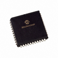
PIC18F448-I/L Microchip Technology, PIC18F448-I/L Datasheet - Page 269

PIC18F448-I/L
Manufacturer Part Number
PIC18F448-I/L
Description
IC,MICROCONTROLLER,8-BIT,PIC CPU,CMOS,LDCC,44PIN,PLASTIC
Manufacturer
Microchip Technology
Series
PIC® 18Fr
Datasheets
1.PIC18LF242-ISO.pdf
(36 pages)
2.PIC18F248-ISO.pdf
(402 pages)
3.PIC18F248-ISO.pdf
(8 pages)
Specifications of PIC18F448-I/L
Rohs Compliant
YES
Core Processor
PIC
Core Size
8-Bit
Speed
40MHz
Connectivity
CAN, I²C, SPI, UART/USART
Peripherals
Brown-out Detect/Reset, LVD, POR, PWM, WDT
Number Of I /o
33
Program Memory Size
16KB (8K x 16)
Program Memory Type
FLASH
Eeprom Size
256 x 8
Ram Size
768 x 8
Voltage - Supply (vcc/vdd)
4.2 V ~ 5.5 V
Data Converters
A/D 8x10b
Oscillator Type
External
Operating Temperature
-40°C ~ 85°C
Package / Case
44-PLCC
Processor Series
PIC18F
Core
PIC
Data Bus Width
8 bit
Data Ram Size
768 B
Interface Type
SPI, I2C, USART
Maximum Clock Frequency
40 MHz
Number Of Programmable I/os
33
Number Of Timers
4
Operating Supply Voltage
2 V to 5.5 V
Maximum Operating Temperature
+ 85 C
Mounting Style
SMD/SMT
3rd Party Development Tools
52715-96, 52716-328, 52717-734, 52712-325, EWPIC18
Development Tools By Supplier
PG164130, DV164035, DV244005, DV164005, PG164120, ICE2000, DV164136, DM163011
Minimum Operating Temperature
- 40 C
On-chip Adc
10 bit, 8 Channel
Lead Free Status / RoHS Status
Contains lead / RoHS non-compliant
For Use With
AC164309 - MODULE SKT FOR PM3 44PLCC444-1001 - DEMO BOARD FOR PICMICRO MCUDVA16XL441 - ADAPTER DEVICE ICE 44PLCCDV007003 - PROGRAMMER UNIVERSAL PROMATE II
Lead Free Status / Rohs Status
Details
Other names
PIC18F448I/L
Available stocks
Company
Part Number
Manufacturer
Quantity
Price
Company:
Part Number:
PIC18F448-I/L
Manufacturer:
Microchip Technology
Quantity:
10 000
- Current page: 269 of 402
- Download datasheet (7Mb)
REGISTER 24-3:
REGISTER 24-4:
© 2006 Microchip Technology Inc.
bit 7-4
bit 3-1
bit 0
bit 7
bit 6-3
bit 2
bit 1
bit 0
bit 7
CONFIG4L: CONFIGURATION REGISTER 4 LOW (BYTE ADDRESS 300006h)
CONFIG2H: CONFIGURATION REGISTER 2 HIGH (BYTE ADDRESS 300003h)
Unimplemented: Read as ‘0’
WDTPS2:WDTPS0: Watchdog Timer Postscale Select bits
111 = 1:128
110 = 1:64
101 = 1:32
100 = 1:16
011 = 1:8
010 = 1:4
001 = 1:2
000 = 1:1
WDTEN: Watchdog Timer Enable bit
1 = WDT enabled
0 = WDT disabled (control is placed on the SWDTEN bit)
Legend:
R = Readable bit
-n = Value when device is unprogrammed
bit 7
Legend:
R = Readable bit
-n = Value when device is unprogrammed
DEBUG: Background Debugger Enable bit
1 = Background Debugger disabled. RB6 and RB7 configured as general purpose I/O pins.
0 = Background Debugger enabled. RB6 and RB7 are dedicated to In-Circuit Debug.
Unimplemented: Read as ‘0’
LVP: Low-Voltage ICSP Enable bit
1 = Low-Voltage ICSP enabled
0 = Low-Voltage ICSP disabled
Unimplemented: Read as ‘0’
STVREN: Stack Full/Underflow Reset Enable bit
1 = Stack Full/Underflow will cause Reset
0 = Stack Full/Underflow will not cause Reset
DEBUG
Note:
R/P-1
U-0
—
The Watchdog Timer postscale select bits configuration used in the PIC18FXXX
devices has changed from the configuration used in the PIC18CXXX devices.
U-0
—
U-0
—
C = Clearable bit
P = Programmable bit
U-0
—
U-0
—
U-0
U-0
—
—
WDTPS2
R/P-1
U = Unimplemented bit, read as ‘0’
u = Unchanged from programmed state
U = Unimplemented bit, read as ‘0’
u = Unchanged from programmed state
U-0
—
WDTPS1
R/P-1
R/P-1
LVP
PIC18FXX8
WDTPS0
R/P-1
U-0
—
DS41159E-page 267
STVREN
WDTEN
R/P-1
R/P-1
bit 0
bit 0
Related parts for PIC18F448-I/L
Image
Part Number
Description
Manufacturer
Datasheet
Request
R

Part Number:
Description:
IC, 8BIT MCU, PIC18F, 40MHZ, LCC-44
Manufacturer:
Microchip Technology
Datasheet:

Part Number:
Description:
IC, 8BIT MCU, PIC18LF, 40MHZ, PLCC-64
Manufacturer:
Microchip Technology
Datasheet:

Part Number:
Description:
IC, 8BIT MCU, PIC18F, 64MHZ, TQFP-80
Manufacturer:
Microchip Technology
Datasheet:

Part Number:
Description:
MCU, MPU & DSP Development Tools CAN/LIN PICtail Plus Daughter Board
Manufacturer:
Microchip Technology
Datasheet:

Part Number:
Description:
IC, 8BIT MCU, PIC18F, 64MHZ, DIP-40
Manufacturer:
Microchip Technology
Datasheet:

Part Number:
Description:
IC, 8BIT MCU, PIC18LF, 40MHZ, PLCC-64
Manufacturer:
Microchip Technology
Datasheet:

Part Number:
Description:
IC, 8BIT MCU, PIC18F, 64MHZ, TQFP-64
Manufacturer:
Microchip Technology

Part Number:
Description:
IC, 8BIT MCU, PIC18F, 64MHZ, TQFP-80
Manufacturer:
Microchip Technology

Part Number:
Description:
8KB, Flash, 768bytes-RAM, 36I/O, 8-bit Family,nanowatt XLP 40 UQFN 5x5x0.5mm TUB
Manufacturer:
Microchip Technology
Datasheet:

Part Number:
Description:
8KB, Flash, 768bytes-RAM, 36I/O, 8-bit Family,nanowatt XLP 40 UQFN 5x5x0.5mm TUB
Manufacturer:
Microchip Technology

Part Number:
Description:
16KB, Flash, 768bytes-RAM, 36I/O, 8-bit Family,nanowatt XLP 40 UQFN 5x5x0.5mm TU
Manufacturer:
Microchip Technology
Datasheet:

Part Number:
Description:
16KB, Flash, 768bytes-RAM, 36I/O, 8-bit Family,nanowatt XLP 40 UQFN 5x5x0.5mm TU
Manufacturer:
Microchip Technology

Part Number:
Description:
32KB, Flash, 1536bytes-RAM, 36I/O, 8-bit Family,nanowatt XLP 40 UQFN 5x5x0.5mm T
Manufacturer:
Microchip Technology
Datasheet:

Part Number:
Description:
32KB, Flash, 1536bytes-RAM, 36I/O, 8-bit Family,nanowatt XLP 40 UQFN 5x5x0.5mm T
Manufacturer:
Microchip Technology

Part Number:
Description:
64KB, Flash, 3968bytes-RAM, 36I/O, 8-bit Family,nanowatt XLP 40 UQFN 5x5x0.5mm T
Manufacturer:
Microchip Technology
Datasheet:


