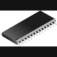
CS4360-KS Cirrus Logic Inc, CS4360-KS Datasheet - Page 4

CS4360-KS
Manufacturer Part Number
CS4360-KS
Description
D/A Converter (D-A) IC
Manufacturer
Cirrus Logic Inc
Datasheet
1.CS4360-KZZ.pdf
(37 pages)
Specifications of CS4360-KS
No. Of Pins
28
No. Of Bits
24 Bit
Mounting Type
Surface Mount
Interface Type
Serial
Package / Case
28-SOIC
Available stocks
Company
Part Number
Manufacturer
Quantity
Price
Part Number:
CS4360-KS EP
Manufacturer:
CIRRUS
Quantity:
20 000
Part Number:
CS4360-KSZ
Manufacturer:
CIRRUS
Quantity:
20 000
LIST OF FIGURES
LIST OF TABLES
4
Figure 1.
Figure 2.
Figure 3.
Figure 4.
Figure 5.
Figure 6.
Figure 7.
Figure 8.
Figure 9.
Figure 10. Double-speed Transition Band (Detail) ........................................................................ 15
Figure 11. Double-speed Passband Ripple ................................................................................... 15
Figure 12. Serial Mode Input Timing ............................................................................................. 16
Figure 13. Control Port Timing - I²C Mode .................................................................................... 17
Figure 14. Control Port Timing - SPI Mode ................................................................................... 18
Figure 15. Left Justified up to 24-Bit Data ..................................................................................... 23
Figure 16. I
Figure 17. Right Justified Data ...................................................................................................... 23
Figure 18. De-emphasis Curve ..................................................................................................... 23
Figure 19. I²C Write ....................................................................................................................... 27
Figure 20. I²C Read ....................................................................................................................... 27
Figure 21. SPI Write ...................................................................................................................... 28
Figure 22. ATAPI Block Diagram .................................................................................................. 32
Table 1. CS4360 Stand-alone Operational Mode............................................................................. 21
Table 2. CS4360 Control Port Operational Mode ............................................................................. 21
Table 3. Single-speed Mode Standard Frequencies ........................................................................ 21
Table 4. Double-speed Mode Standard Frequencies ....................................................................... 21
Table 5. Quad-speed Mode Standard Frequencies ......................................................................... 22
Table 6. Digital Interface Format - Stand-alone Mode...................................................................... 22
Table 7. Power Supply Control Sections .......................................................................................... 25
Table 8. Digital Interface Formats - Control Port Mode .................................................................... 30
Table 9. ATAPI Decode .................................................................................................................... 32
Table 10. Example Digital Volume Settings ..................................................................................... 33
8. REFERENCES ........................................................................................................................ 36
9. PACKAGE DIMENSIONS ....................................................................................................... 37
Typical Connection Diagram .......................................................................................... 7
Output Test Load ......................................................................................................... 10
Maximum Loading ........................................................................................................ 10
Single-speed Stopband Rejection ................................................................................ 14
Single-speed Transition Band ...................................................................................... 14
Single-speed Transition Band (Detail) ......................................................................... 14
Single-speed Passband Ripple .................................................................................... 14
Double-speed Stopband Rejection .............................................................................. 14
Double-speed Transition Band ..................................................................................... 14
2
S, up to 24-Bit Data ................................................................................................... 23
CS4360
DS517F2


