AD630AD Analog Devices Inc, AD630AD Datasheet - Page 8
AD630AD
Manufacturer Part Number
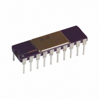
AD630AD
Description
MODULATOR / DEMODULATOR IC
Manufacturer
Analog Devices Inc
Datasheet
1.AD630JNZ.pdf
(12 pages)
Specifications of AD630AD
Rf Type
Balanced
Supply Voltage Range
± 5V To �� 16.5V
Rf Ic Case Style
DIP
No. Of Pins
20
Operating Temperature Range
-25°C To +85°C
Peak Reflow Compatible (260 C)
No
Leaded Process Compatible
No
Rohs Status
RoHS non-compliant
Function
Modulator/Demodulator
Frequency
2MHz
Package / Case
20-CDIP (0.300", 7.62mm)
Mounting Type
Through Hole
Rohs Compliant
No
Lead Free Status / RoHS Status
Contains lead / RoHS non-compliant
Available stocks
Company
Part Number
Manufacturer
Quantity
Price

Part Number:
AD630AD
Manufacturer:
ADI/亚德诺
Quantity:
20 000


AD630
the system input tied to 0 V, and a switching or carrier wave-
form applied to the comparator, a low level square wave will
appear at the output. The differential offset adjustment potenti-
ometers can be used to null the amplitude of this square wave
(Pins 3 and 4). The common-mode offset adjustment can be
used to zero the residual dc output voltage (Pins 5 and 6).
These functions should be implemented using 10k trim poten-
tiometers with wipers connected directly to Pin 8 as shown in
Figures 9a and 9b.
CHANNEL STATUS OUTPUT
The channel status output, Pin 7, is an open collector output
referenced to –V
input channels is active. The output will be active (pulled low)
when Channel A is selected. This output can also be used to
supply positive feedback around the comparator. This produces
hysteresis which serves to increase noise immunity. Figure 7
shows an example of how hysteresis may be implemented. Note
that the feedback signal is applied to the inverting (–) terminal
of the comparator to achieve positive feedback. This is because
the open collector channel status output inverts the output sense
of the internal comparator.
The channel status output may be interfaced with TTL inputs
as shown in Figure 8. This circuit provides appropriate level
shifting from the open-collector AD630 channel status output to
TTL inputs.
APPLICATIONS: BALANCED MODULATOR
Perhaps the most commonly used configuration of the AD630 is
the balanced modulator. The application resistors provide precise
symmetric gains of ± 1 and ± 2. The ± 1 arrangement is shown in
Figure 9a and the ± 2 arrangement is shown in Figure 9b. These
cases differ only in the connection of the 10 kΩ feedback resistor
(Pin 14) and the compensation capacitor (Pin 12). Note the use
of the 2.5 kΩ bias current compensation resistors in these
examples. These resistors perform the identical function in the
± 1 gain case. Figure 10 demonstrates the performance of the
AD630
Figure 8. Channel Status—TTL Interface
Figure 7. Comparator Hysteresis
S
7
8
100k
that can be used to indicate which of the two
–15V
10
+15V
100
2N2222
9
6.8k
1M
22k
IN 914s
+5V
8
7
100k
100k
–15V
TTL INPUT
+5V
–8–
AD630 when used to modulate a 100 kHz square wave carrier
with a 10 kHz sinusoid. The result is the double sideband sup-
pressed carrier waveform.
These balanced modulator topologies accept two inputs, a signal
(or modulation) input applied to the amplifying channels and a
reference (or carrier) input applied to the comparator.
Figure 9a. AD630 Configured as a Gain-of-One Balanced
Modulator
Figure 9b. AD630 Configured as a Gain-of-Two Balanced
Modulator
MODULATION
MODULATION
Figure 10. Gain-of-Two Balanced Modulator Sample
Waveforms
CARRIER
CARRIER
INPUT
INPUT
INPUT
INPUT
10V
5V
20
18
19
10
17
1
2
20
17
18
19
10
9
1
2
9
2.5k
2.5k
2.5k
2.5k
10k
10k
AMP A
AMP B
AMP A
COMP
AMP B
COMP
6
6
CM
ADJ
CM
ADJ
B
A
A
B
5V
5
5
AD630
AD630
10k
–V
10k
–V
8
8
–V
–V
4
4
S
10k
S
10k
DIFF
ADJ
DIFF
ADJ
20 s
3
3
10k
5k
10k
5k
12
11
13
14
15
16
12
11
13
14
15
16
7
7
MODULATION
INPUT
CARRIER
INPUT
OUTPUT
SIGNAL
MODULATED
OUTPUT
SIGNAL
MODULATED
OUTPUT
SIGNAL
REV. E
+V
+V
S
S
Related parts for AD630AD
Image
Part Number
Description
Manufacturer
Datasheet
Request
R

Part Number:
Description:
±1.7g Dual-Axis IMEMS Accelerometer Evaluation Board
Manufacturer:
Analog Devices Inc
Datasheet:

Part Number:
Description:
Inertial Sensor Evaluation System
Manufacturer:
Analog Devices Inc
Datasheet:
Part Number:
Description:
Manufacturer:
Analog Devices Inc
Datasheet:
Part Number:
Description:
Manufacturer:
Analog Devices Inc
Datasheet:
Part Number:
Description:
Manufacturer:
Analog Devices Inc
Datasheet:
Part Number:
Description:
Manufacturer:
Analog Devices Inc
Datasheet:
Part Number:
Description:
Manufacturer:
Analog Devices Inc
Datasheet:
Part Number:
Description:
Manufacturer:
Analog Devices Inc
Datasheet:
Part Number:
Description:
Manufacturer:
Analog Devices Inc
Datasheet:
Part Number:
Description:
Manufacturer:
Analog Devices Inc
Datasheet:
Part Number:
Description:
Manufacturer:
Analog Devices Inc
Datasheet:
Part Number:
Description:
Manufacturer:
Analog Devices Inc
Datasheet:
Part Number:
Description:
Manufacturer:
Analog Devices Inc
Datasheet: