AD630AD Analog Devices Inc, AD630AD Datasheet - Page 10
AD630AD
Manufacturer Part Number
AD630AD
Description
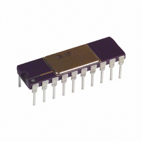
MODULATOR / DEMODULATOR IC
Manufacturer
Analog Devices Inc
Datasheet
1.AD630JNZ.pdf
(12 pages)
Specifications of AD630AD
Rf Type
Balanced
Supply Voltage Range
± 5V To �� 16.5V
Rf Ic Case Style
DIP
No. Of Pins
20
Operating Temperature Range
-25°C To +85°C
Peak Reflow Compatible (260 C)
No
Leaded Process Compatible
No
Rohs Status
RoHS non-compliant
Function
Modulator/Demodulator
Frequency
2MHz
Package / Case
20-CDIP (0.300", 7.62mm)
Mounting Type
Through Hole
Rohs Compliant
No
Lead Free Status / RoHS Status
Contains lead / RoHS non-compliant
Available stocks
Company
Part Number
Manufacturer
Quantity
Price

Part Number:
AD630AD
Manufacturer:
ADI/亚德诺
Quantity:
20 000


AD630
LOCK-IN AMPLIFIER APPLICATIONS
Lock-in amplification is a technique used to separate a small,
narrow-band signal from interfering noise. The lock-in amplifier
acts as a detector and narrow-band filter combined. Very small
signals can be detected in the presence of large amounts of
uncorrelated noise when the frequency and phase of the desired
signal are known.
The lock-in amplifier is basically a synchronous demodulator
followed by a low-pass filter. An important measure of performance
in a lock-in amplifier is the dynamic range of its demodulator.
The schematic diagram of a demonstration circuit which exhibits
the dynamic range of an AD630 as it might be used in a lock-in
amplifier is shown in Figure 14. Figure 15 is an oscilloscope
photo demonstrating the large dynamic range of the AD630.
The photo shows the recovery of a signal modulated at 400 Hz
from a noise signal approximately 100,000 times larger.
ATTENUATION
MODULATED
BAND-LIMITED
WHITE NOISE
A
CARRIER
CLIPPED
400Hz
0.1Hz
100dB
Figure 13. AC Bridge Waveforms (1 V Excitation)
3
C. 200mV/DIV
CARRIER
PHASE
REFERENCE
AD542
Figure 14. Lock-In Amplifier
B
16
[
17
14
10
9
1
2.5k
2.5k
10k
5k
19
15
20
AD630
B. 200mV/DIV
T
T
A
B
10k
A. 200mV/DIV
13
]
R
500 s/DIV
LOW-PASS
FILTER
AD542
C
100R
100R
C
OUTPUT
–10–
The test signal is produced by modulating a 400 Hz carrier with
a 0.1 Hz sine wave. The signals produced, for example, by
chopped radiation (i.e., IR, optical) detectors may have similar
low frequency components. A sinusoidal modulation is used for
clarity of illustration. This signal is produced by a circuit similar
to Figure 9b and is shown in the upper trace of Figure 15. It is
attenuated 100,000 times normalized to the output, B, of the
summing amplifier. A noise signal that might represent, for
example, background and detector noise in the chopped radia-
tion case, is added to the modulated signal by the summing
amplifier. This signal is simply band limited clipped white noise.
Figure 15 shows the sum of attenuated signal plus noise in the
center trace. This combined signal is demodulated synchro-
nously using phase information derived from the modulator,
and the result is low-pass filtered using a 2-pole simple filter
which also provides a gain of 100 to the output. This recovered
signal is the lower trace of Figure 15.
The combined modulated signal and interfering noise used for
this illustration is similar to the signals often requiring a lock-in
amplifier for detection. The precision input performance of the
AD630 provides more than 100 dB of signal range and its
dynamic response permits it to be used with carrier frequencies
more than two orders of magnitude higher than in this example.
A more sophisticated low-pass output filter will aid in rejecting
wider bandwidth interference.
100
0%
90
10
Figure 15. Lock-In Amplifier Waveforms
5V
5mV
5V
5s
MODULATED SIGNAL (A)
(UNATTENUATED)
ATTENUATED SIGNAL
PLUS NOISE (B)
OUTPUT
REV. E
Related parts for AD630AD
Image
Part Number
Description
Manufacturer
Datasheet
Request
R

Part Number:
Description:
±1.7g Dual-Axis IMEMS Accelerometer Evaluation Board
Manufacturer:
Analog Devices Inc
Datasheet:

Part Number:
Description:
Inertial Sensor Evaluation System
Manufacturer:
Analog Devices Inc
Datasheet:
Part Number:
Description:
Manufacturer:
Analog Devices Inc
Datasheet:
Part Number:
Description:
Manufacturer:
Analog Devices Inc
Datasheet:
Part Number:
Description:
Manufacturer:
Analog Devices Inc
Datasheet:
Part Number:
Description:
Manufacturer:
Analog Devices Inc
Datasheet:
Part Number:
Description:
Manufacturer:
Analog Devices Inc
Datasheet:
Part Number:
Description:
Manufacturer:
Analog Devices Inc
Datasheet:
Part Number:
Description:
Manufacturer:
Analog Devices Inc
Datasheet:
Part Number:
Description:
Manufacturer:
Analog Devices Inc
Datasheet:
Part Number:
Description:
Manufacturer:
Analog Devices Inc
Datasheet:
Part Number:
Description:
Manufacturer:
Analog Devices Inc
Datasheet:
Part Number:
Description:
Manufacturer:
Analog Devices Inc
Datasheet: