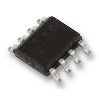
SI-8005Q Allegro Microsystems Inc, SI-8005Q Datasheet - Page 8

SI-8005Q
Manufacturer Part Number
SI-8005Q
Description
IC, BUCK, REG, 3.5A, 8HSOP
Manufacturer
Allegro Microsystems Inc
Datasheet
1.SI-8005Q.pdf
(12 pages)
Specifications of SI-8005Q
Primary Input Voltage
28V
No. Of Outputs
1
Output Voltage
24V
Output Current
3.5A
Voltage Regulator Case Style
HSOP
No. Of Pins
8
Operating Temperature Range
-30°C To +85°C
Base
RoHS Compliant
Package / Case
HSOP
Available stocks
Company
Part Number
Manufacturer
Quantity
Price
Company:
Part Number:
SI-8005Q
Manufacturer:
NEC
Quantity:
1 600
SI-8005Q
Using the SI-8005Q as an LED Driver
SI-8005Q also can be configured as a high-efficiency constant
current LED driver. Figure 2 is a typical circuit diagram for this
application.
LED current is set by the formula below:
Note that LED current runs through the IC. Therefore, choose
a proper power rating for R3, based on actual power dissipa-
Figure 2. Typical application circuit for driving LEDs
Component
V
I I N
C1 (2 ea)
C2 (2 ea)
G N D
C1
C4
R2
R5
C3
R3
L1
Di
R5
46.4 kΩ
560 pF
7
8
3
S S
EN
2
I
I I N
LED
1.5 MΩ / 0.5 W
LEDs in Series
C O M P
10 μF / 50 V
22 μF / 16 V
10 nF / 50 V
0.5 Ω / 1 W
S I - 8005Q
5 A / 60 V
Rating
69.8 kΩ
470 pF
= V
10 μH
6
R3
C3
4
REF
1
/ R
B S
G N D
Step-Down Switching Regulator with Current-Mode Control
S W
FB
2
4
360 pF
100 kΩ
.
3
5
5
C4
Di
115 Northeast Cutoff, Box 15036
Allegro MicroSystems, Inc.
Worcester, Massachusetts 01615-0036 (508) 853-5000
www.allegromicro.com
LEDs
Input capacitor
Output capacitor
Bootstrap capacitor
Schottky barrier diode
Choke coil
Current sensing resistor
Trim resistor for improved
response time
Phase compensation capacitor
Phase compensation resistor
V
R2
FB
L1
Description
G N D
C2
V
O
Figure 3. Total LED driving current for 4 LEDs in series
tion and derating based on application ambient temperature. The
power dissipation for the resistor is calculated as:
PWM Dimming By pulsing EN input at 100 to 300 Hz, LED
brightness can be dimmed. Figure 3 shows LED current versus
the duty cycle of the EN pin. The test was performed with four
LEDs in series. The waveforms in figure 4 show how it works.
The EN pin peak voltage should be in the range 3 to 5 V,
1200
1000
800
600
400
200
0
0
20
IC Switching
P
D
Figure 4. PWM dimming timing example
= I
V
40
I
V
Duty Cycle (%)
LED
LED
SW
EN
× V
REF
60
.
80
1000 mA
500 mA
350 mA
150 mA
100
8


