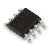
SI-8005Q Allegro Microsystems Inc, SI-8005Q Datasheet - Page 7

SI-8005Q
Manufacturer Part Number
SI-8005Q
Description
IC, BUCK, REG, 3.5A, 8HSOP
Manufacturer
Allegro Microsystems Inc
Datasheet
1.SI-8005Q.pdf
(12 pages)
Specifications of SI-8005Q
Primary Input Voltage
28V
No. Of Outputs
1
Output Voltage
24V
Output Current
3.5A
Voltage Regulator Case Style
HSOP
No. Of Pins
8
Operating Temperature Range
-30°C To +85°C
Base
RoHS Compliant
Package / Case
HSOP
Available stocks
Company
Part Number
Manufacturer
Quantity
Price
Company:
Part Number:
SI-8005Q
Manufacturer:
NEC
Quantity:
1 600
SI-8005Q
amplifier. The combination of a series-connected capacitor and
resistor sets the combination of a pole and zero frequency point
that decide the characteristics of the control system. The DC gain
of the voltage feedback loop is calculated by the following equa-
tion:
where
The system has two important poles. One is set by the phase
compensation capacitor (C3) and the output resistor of the error
amplifier. The other is set by the output capacitor and load resis-
tor. These poles are calculated by the following equations:
where G
The system has one important zero point. This is set by the phase
compensation capacitor (C3) and phase compensation resistor
(R3). The zero point is shown by the following equation:
If the value of the output capacitor is the large or if it has a high
ESR, the system may have another important zero point. This
zero point would be set by the ESR and capacitance of the output
capacitor. The zero point is shown by the following equation:
In this case a third pole, which is set by the phase compensation
capacitor (C6) and phase compensation resistor (R3), is used to
compensate the effect of the ESR zero point on the loop gain.
The pole is shown by the following equation:
V
A
G
Rl is the load resistor value.
FB
EA
CS
is the feedback voltage (0.5 V),
is the error amplifier voltage gain,
is the current sense transconductance, and
EA
is the error amplifier transconductance.
Adc
fESR
fp
fp
fp
fz
Rl
1
1
3
2
2
2
2
2
2
π
Gcs
π
π
π
π
G
C
C
C
C
C
A
1
1
1
EA
3
2
3
1
6
EA
2
Step-Down Switching Regulator with Current-Mode Control
A
RESR
R
R
Rl
EA
Vout
3
V
3
FB
.
,
.
,
,
.
115 Northeast Cutoff, Box 15036
Allegro MicroSystems, Inc.
Worcester, Massachusetts 01615-0036 (508) 853-5000
www.allegromicro.com
(1)
(2)
(3)
(4)
(5)
(6)
The goal of phase compensation design is to shape the con-
verter transfer function to get the required loop gain. The system
crossover frequency, where the feedback loop has unity gain, is
important. Lower crossover frequencies result in slower line and
load transient responses. On the other hand, higher crossover fre-
quencies cause system instability. A good standard is to adjust the
crossover frequency to approximately one-tenth of the switching
frequency.
The optimal selection of phase compensation components can be
determined using the following procedure:
1. Choose the phase compensation resistor (R3) to adjust the
required crossover frequency. R3 value is calculated by the fol-
lowing equation:
where f
adjusted to less than one-tenth of the switching frequency.
2. Choose the phase compensation capacitor (C3) to get the
required phase margin. For applications that have typical inductor
values, adjusting the compensation zero point to less than one-
quarter of crossover frequency provides sufficient phase margin.
The value of C3 is calculated by the following equation:
where R3 is the phase compensation resistor.
3. It is necessary to determine whether a second compensation
capacitor (C6) is required. It is required if the ESR zero point of
the output capacitor is less than half of the switching frequency,
expressed as follows:
If this is the case, add the second compensation capacitor (C6)
and adjust ESR zero frequency (f
the following equation:
R
3
c
is the required crossover frequency. This is usually
2
GEA
π
C
2
GCS
2
π
C
C
fc
3
6
C
Vout
VFB
2
2
1
C
π
2
RESR
p3
2
R
R
4
RESR
π
). C6 value is calculated by
3
3
GEA
C
fc
2
fs
2
GCS
0
.
,
1 .
.
fs
Vout
V
FB
, (7)
(10)
(8)
(9)
7


