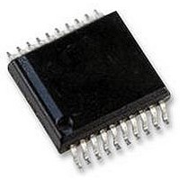
TB6608FNG Toshiba, TB6608FNG Datasheet - Page 3

TB6608FNG
Manufacturer Part Number
TB6608FNG
Description
STEPPER MOTOR DRIVE, 13V 0.8A SSOP20
Manufacturer
Toshiba
Datasheet
1.TB6608FNG.pdf
(30 pages)
Specifications of TB6608FNG
No. Of Outputs
2
Output Current
600mA
Output Voltage
15V
Supply Voltage Range
2.7V To 5.5V, 2.5V To 13.5V
Driver Case Style
SSOP
No. Of Pins
20
Operating Temperature Range
-20°C To +85°C
Motor Type
Stepper
Rohs Compliant
Yes
Function
Driver
Vopmax (vm*)
13.5V (15V)
Io (lpeak)
0.6A (0.8A)
Excitation
1/8 step
I/f
CLK input
Mixed Decay Mode
no
Package
SSOP24
Rohs Compatible†
yes
Lead Free Status / RoHS Status
Lead free / RoHS Compliant
Available stocks
Company
Part Number
Manufacturer
Quantity
Price
Company:
Part Number:
TB6608FNG
Manufacturer:
TPT
Quantity:
10 810
Part Number:
TB6608FNG
Manufacturer:
TOSHIBA/东芝
Quantity:
20 000
Company:
Part Number:
TB6608FNG(C8,EL,HJ
Manufacturer:
TI
Quantity:
12
Pin Function
Pin Assignment
Pin No.
10
12
13
14
15
16
17
18
19
20
11
1
2
3
4
5
6
7
8
9
CW/CCW
ENABLE
Symbol
RESET
STBY
OSC
GND
BO2
RFB
BO1
AO2
AO1
DCY
V
RFA
MO
M1
M2
V
TQ
CK
CC
M
CW/CCW
Power supply pin for logic block
Standby input
Connection pin for an external capacitor
used for internal oscillation
Excitation mode setting input 1
Excitation mode setting input 2
Power supply pin for output
Rotation direction select input
B-phase output 2
Connection pin for a B-phase output
current detection resistor
B-phase output 1
A-phase output 2
Connection pin for an A-phase output
current detection resistor
A-phase output 1
Reset input
Ground
Monitor output
Decay setting input
Enable input
Clock input
Vref setting input
STBY
OSC
BO2
RFB
BO1
V
V
M1
M2
CC
M
Functional Description
1
2
3
4
5
6
7
8
9
10
3
V
See the Input Signals and Operating Modes table.
See the Excitation Mode Settings table.
See the Excitation Mode Settings table.
V
See the Input Signals and Operating Modes table.
Connect BO2 to a motor coil pin.
Connect BO1 to a motor coil pin.
Connect AO2 to a motor coil pin.
Connect AO1 to a motor coil pin.
See the Input Signal and Operating Modes table.
Initial state: MO = Low (open drain, pulled up by an
external resistor)
See the Vref Voltage Setting table.
See the Fast-Decay Time Inserted During the Current
Decay Period table.
See the Input Signal and Operating Modes table.
CC (opr)
M (opr)
20
19
18
17
16
15
14
13
12
11
= 2.5 to 13.5 V
= 2.7 to 5.5 V
MO
CK
ENABLE
DCY
TQ
GND
RESET
AO1
RFA
AO2
Remarks
TB6608FNG
2007-12-17


