AD779KD Analog Devices Inc, AD779KD Datasheet - Page 9
AD779KD
Manufacturer Part Number
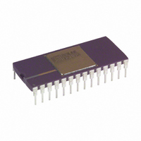
AD779KD
Description
IC, ADC, 14BIT, 128KSPS, DIP-28
Manufacturer
Analog Devices Inc
Datasheet
1.AD779JNZ.pdf
(12 pages)
Specifications of AD779KD
Resolution (bits)
14bit
Sampling Rate
128kSPS
Input Channel Type
Single Ended
Data Interface
Parallel
Supply Current
25mA
Digital Ic Case Style
DIP
No. Of Pins
28
Rohs Status
RoHS non-compliant
Number Of Bits
14
Sampling Rate (per Second)
128k
Number Of Converters
1
Power Dissipation (max)
745mw
Voltage Supply Source
Dual ±
Operating Temperature
0°C ~ 70°C
Mounting Type
Through Hole
Package / Case
28-CDIP (0.600", 15.24mm)
Lead Free Status / RoHS Status
Contains lead / RoHS non-compliant
Available stocks
Company
Part Number
Manufacturer
Quantity
Price


BIPOLAR RANGE INPUTS
The connections for the bipolar mode are shown in Figure 5. In
this mode, data output coding will be twos complement binary.
This circuit will allow approximately 25 mV of offset trim
range ( 40 LSB) and 0.5% of gain trim range ( 80 LSB).
Either or both of the trim pots can be replaced with 50
fixed resistors if the AD779 accuracy limits are sufficient for the
application. If the pins are shorted together, the additional offset
and gain errors will be approximately 80 LSB.
To trim bipolar zero to its nominal value, apply a signal 1/2 LSB
below midrange (–0.305 mV for a 5 V range) and adjust R1
until the major carry transition is located (11 1111 1111 1111 to
00 0000 0000 0000). To trim the gain, apply a signal 1 1/2 LSB
below full scale (+4.9991 V for a 5 V range) and adjust R2 to
give the last positive transition (01 1111 1111 1110 to 01 1111
1111 1111). These trims are interactive so several iterations may
be necessary for convergence.
A single pass calibration can be done by substituting a bipolar
offset trim (error at minus full scale) for the bipolar zero trim
(error at midscale), using the same circuit. First, apply a signal
1/2 LSB above minus full scale (–4.9997 V for a 5 V range)
and adjust R1 until the minus full-scale transition is located
(10 0000 0000 0000 to 10 000 000 0001). Then perform the
gain error trim as outlined above.
UNIPOLAR RANGE INPUTS
Offset and gain errors can be trimmed out by using the configu-
ration shown in Figure 6. This circuit allows approximately
range ( 80 LSB).
REV. B
25 mV of offset trim range ( 40 LSB) and 0.5% of gain trim
Figure 6. Unipolar Input Connections with Gain and
Offset Trims
Figure 5. Bipolar Input Connections with Gain and
Offset Trims
1%
–9–
The first transition (from 00 0000 0000 0000 to 00 0000 0000
0001) should nominally occur for an input level of +1/2 LSB
(0.305 mV above ground for a 10 V range). To trim unipolar
zero to this nominal value, apply a 0.305 mV signal to AIN and
adjust R1 until the first transition is located.
The gain trim is done by adjusting R2. If the nominal value is
required, apply a signal 1 1/2 LSB below full scale (9.9997 V for
a 10 V range) and adjust R2 until the last transition is located
(11 1111 1111 1110 to 11 1111 1111 1111).
If offset adjustment is not required, BIPOFF should be con-
nected directly to AGND. If gain adjustment is not required, R2
should be replaced with a fixed 50
REF
error will be approximately 1%.
REFERENCE DECOUPLING
It is recommended that a 10 F tantalum capacitor be
connected between REF
effect of improving the S/N+D ratio through filtering possible
broadband noise contributions from the voltage reference.
BOARD LAYOUT
Designing with high resolution data converters requires careful
attention to board layout. Trace impedance is a significant issue.
A 1.22 mA current through a 0.5
drop of 0.6 mV, which is 1 LSB at the 14-bit level for a 10 V
full-scale span. In addition to ground drops, inductive and
capacitive coupling need to be considered, especially when high
accuracy analog signals share the same board with digital signals.
Finally, power supplies need to be decoupled in order to filter
out ac noise.
Analog and digital signals should not share a common path.
Each signal should have an appropriate analog or digital return
routed close to it. Using this approach, signal loops enclose a
small area, minimizing the inductive coupling of noise. Wide PC
tracks, large gauge wire, and ground planes are highly recom-
mended to provide low impedance signal paths. Separate analog
and digital ground planes are also desirable, with a single
interconnection point to minimize ground loops. Analog signals
should be routed as far as possible from digital signals and
should cross them at right angles.
The AD779 incorporates several features to help the user’s layout.
Analog pins (V
V
addition, the 10 M input impedance of AIN minimizes input
trace impedance errors. Finally, ground currents have been
minimized by careful circuit design. Current through AGND is
200 A, with no code dependent variation. The current through
DGND is dominated by the return current for DB13–DB0 and
EOC.
SUPPLY DECOUPLING
The AD779 power supplies should be well filtered, well regulated,
and free from high frequency noise. Switching power supplies
are not recommended due to their tendency to generate spikes
which can induce noise in the analog system.
Decoupling capacitors should be used as close as possible to all
power supply pins. A 10 F tantalum capacitor in parallel with a
0.1 F ceramic capacitor provides adequate decoupling.
CC
) are adjacent to help isolate analog from digital signals. In
OUT
is connected directly to REF
BE
) AIN, AGND, REF
IN
(Pin 9) and ground. This has the
trace will develop a voltage
IN
OUT
1% metal film resistor. If
, the additional gain
, REF
IN
, BIPOFF,
AD779
Related parts for AD779KD
Image
Part Number
Description
Manufacturer
Datasheet
Request
R

Part Number:
Description:
±1.7g Dual-Axis IMEMS Accelerometer Evaluation Board
Manufacturer:
Analog Devices Inc
Datasheet:

Part Number:
Description:
Inertial Sensor Evaluation System
Manufacturer:
Analog Devices Inc
Datasheet:
Part Number:
Description:
Manufacturer:
Analog Devices Inc
Datasheet:
Part Number:
Description:
Manufacturer:
Analog Devices Inc
Datasheet:
Part Number:
Description:
Manufacturer:
Analog Devices Inc
Datasheet:
Part Number:
Description:
Manufacturer:
Analog Devices Inc
Datasheet:
Part Number:
Description:
Manufacturer:
Analog Devices Inc
Datasheet:
Part Number:
Description:
Manufacturer:
Analog Devices Inc
Datasheet:
Part Number:
Description:
Manufacturer:
Analog Devices Inc
Datasheet:
Part Number:
Description:
Manufacturer:
Analog Devices Inc
Datasheet:
Part Number:
Description:
Manufacturer:
Analog Devices Inc
Datasheet:
Part Number:
Description:
Manufacturer:
Analog Devices Inc
Datasheet:
Part Number:
Description:
Manufacturer:
Analog Devices Inc
Datasheet: