AD779KD Analog Devices Inc, AD779KD Datasheet - Page 10
AD779KD
Manufacturer Part Number
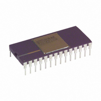
AD779KD
Description
IC, ADC, 14BIT, 128KSPS, DIP-28
Manufacturer
Analog Devices Inc
Datasheet
1.AD779JNZ.pdf
(12 pages)
Specifications of AD779KD
Resolution (bits)
14bit
Sampling Rate
128kSPS
Input Channel Type
Single Ended
Data Interface
Parallel
Supply Current
25mA
Digital Ic Case Style
DIP
No. Of Pins
28
Rohs Status
RoHS non-compliant
Number Of Bits
14
Sampling Rate (per Second)
128k
Number Of Converters
1
Power Dissipation (max)
745mw
Voltage Supply Source
Dual ±
Operating Temperature
0°C ~ 70°C
Mounting Type
Through Hole
Package / Case
28-CDIP (0.600", 15.24mm)
Lead Free Status / RoHS Status
Contains lead / RoHS non-compliant
Available stocks
Company
Part Number
Manufacturer
Quantity
Price


AD779
An effort should be made to minimize the trace length between
the capacitor leads and the respective converter power supply
and common pins. The circuit layout should attempt to locate
the AD779, associated analog input circuitry and interconnec-
tions as far as possible from logic circuitry. A solid analog
ground plane around the AD779 will isolate large switching
ground currents. For these reasons, the use of wire wrap circuit
construction is not recommended; careful printed circuit con-
struction is preferred.
GROUNDING
If a single AD779 is used with separate analog and digital
ground planes, connect the analog ground plane to AGND and
the digital ground plane to DGND keeping lead lengths as short
as possible. Then connect AGND and DGND together at the
AD779. If multiple AD779s are used or the AD779 shares
analog supplies with other components, connect the analog and
digital returns together once at the power supplies rather than at
each chip. This prevents large ground loops which inductively
couple noise and allow digital currents to flow through the
analog system.
USE OF EXTERNAL VOLTAGE REFERENCE
The AD779 features an on-chip voltage reference. For improved
gain accuracy over temperature, a high performance external
voltage reference may be used in place of the on-chip reference.
The AD586 and AD588 are popular references appropriate for
use with high resolution converters. The AD586 is a low cost
reference which utilizes a buried Zener architecture to provide
low noise and drift. The AD588 is a higher performance refer-
ence which uses a proprietary ion-implanted buried Zener diode
in conjunction with laser-trimmed thin-film resistors for low off-
set and low drift.
Figure 7 shows the use of the AD586 with the AD779 in a bipo-
lar input mode. Over the 0 C to +70 C range, the AD586 L-grade
exhibits less than a 2.25 mV output change from its initial value
at 25 C. REF
this change becomes effectively 4.5 mV. When applied to the
AD779, this results in a total gain drift of 0.09% FSR which is
an improvement over the on-chip reference performance of
0.11% FSR. A noise-reduction capacitor, C
This capacitor reduces the broadband noise of the AD586 out-
put, thereby optimizing the overall ac and dc performance of the
AD779.
Figure 8 shows the AD779 in unipolar input mode with the
AD588 reference. The AD588 output is accurate to 0.65 mV
Figure 7. Bipolar Input with Gain and Offset Trims
IN
, (Pin 9) scales its input by a factor of two; thus,
N
, has been shown.
–10–
from its value at 25 C over the 0 C to 70 C range. This results
in a 0.06% FSR total gain drift for the AD779, which is a sub-
stantial improvement over the on-chip reference performance of
0.11% FSR. A noise-reduction network on Pins 4, 6 and 7 has
been shown. The 1 F capacitors form low pass filters with the
internal resistance of the AD588 Zener and amplifier cells and
external resistance. This reduces the high frequency noise of
the AD588, providing optimum ac and dc performance of the
AD779.
INTERFACING THE AD779 TO MICROPROCESSORS
The I/O capabilities of the AD779 allow direct interfacing to
general purpose and DSP microprocessor buses. The asynchro-
nous conversion control feature allows complete flexibility and
control with minimal external hardware.
The following examples illustrate typical AD779 interface
configurations.
AD779 TO TMS320C25
In Figure 9 the AD779 is mapped into the TMS320C25 I/O
space. AD779 conversions are initiated by issuing an OUT
instruction to Port 1. EOC status and the conversion result are
read in with an IN instruction to Port 1. A single wait state is
inserted by generating the processor READY input from IS,
Port 1 and MSC. This configuration supports processor clock
speeds of 20 MHz and is capable of supporting processor clock
speeds of 40 MHz if a NOP instruction follows each AD779
read instruction.
Figure 8. Unipolar Input with Gain and Offset Trims
Figure 9. AD779 to TMS320C25 Interface
REV. B
Related parts for AD779KD
Image
Part Number
Description
Manufacturer
Datasheet
Request
R

Part Number:
Description:
±1.7g Dual-Axis IMEMS Accelerometer Evaluation Board
Manufacturer:
Analog Devices Inc
Datasheet:

Part Number:
Description:
Inertial Sensor Evaluation System
Manufacturer:
Analog Devices Inc
Datasheet:
Part Number:
Description:
Manufacturer:
Analog Devices Inc
Datasheet:
Part Number:
Description:
Manufacturer:
Analog Devices Inc
Datasheet:
Part Number:
Description:
Manufacturer:
Analog Devices Inc
Datasheet:
Part Number:
Description:
Manufacturer:
Analog Devices Inc
Datasheet:
Part Number:
Description:
Manufacturer:
Analog Devices Inc
Datasheet:
Part Number:
Description:
Manufacturer:
Analog Devices Inc
Datasheet:
Part Number:
Description:
Manufacturer:
Analog Devices Inc
Datasheet:
Part Number:
Description:
Manufacturer:
Analog Devices Inc
Datasheet:
Part Number:
Description:
Manufacturer:
Analog Devices Inc
Datasheet:
Part Number:
Description:
Manufacturer:
Analog Devices Inc
Datasheet:
Part Number:
Description:
Manufacturer:
Analog Devices Inc
Datasheet: