169409 Tyco Electronics, 169409 Datasheet - Page 3
169409
Manufacturer Part Number
169409
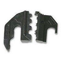
Description
DIE SET, SOLISTRAND
Manufacturer
Tyco Electronics
Series
SOLISTRANDr
Type
Die Setr
Specifications of 169409
Crimp Application
Connectors
Wire Area Size Max
6.6mm2
Wire Area Size Min
0.25mm2
Wire Size Awg Max
10AWG
Wire Size Awg Min
22AWG
Wire Size Swg Max
6
Wire Size Swg Min
29
Product
Crimping, Stripping & Cutting Tools & Drills
Lead Free Status / RoHS Status
na
For Use With
SOLISTRAND Terminals and Splices


5.2. Inspection
Regular inspections should be performed to ensure
the quality and reliability of the tool. Though
recommendations call for at least one inspection a
month, the inspection frequency should be based
upon amount of use, working conditions, operator
training and skill, and established company
standards. Inspect the tool as follows:
6. RATCHET INSPECTION AND ADJUSTMENT
Obtain a 0.025 mm [.001 in.]--thick shim that is
suitable for checking the clearance between the
bottoming surfaces of the crimping dies, and proceed
as follows:
Rev D
3. Lubricate all pins, pivot points, and bearing
surfaces with a thin coat of SAE 20 motor oil.
4. When the tool is not in use, keep it in the tool kit
and store in a clean, dry area.
1. Remove all lubrication and accumulated film by
immersing the tool (handles partially closed) in a
suitable commercial degreaser that will not affect
paint or plastic material.
2. Make certain that all screws are in place and
secured.
3. Close tool handles until ratchet releases, then
allow them to open freely. If they do not open
quickly and fully, the spring is defective.
4. Inspect the head assembly for worn or broken
components.
NOTE
1. Select a product and wire (maximum size)
appropriate for the dies.
2. Position the product and wire between the
crimping dies, according to Section 4, CRIMPING
PROCEDURE.
3. Squeeze the tool handles together until the
ratchet releases. Hold the tool handles in this
position, maintaining sufficient pressure to keep the
dies closed.
4. Check the clearance between the bottoming
surfaces of the crimping dies. If the clearance is
0.025 mm [.001 in.] or less, the ratchet is
satisfactory. If the clearance exceeds 0.025 mm
[.001 in.], the ratchet is out of adjustment and must
be adjusted.
i
A die set must be installed in the tool for this
procedure.
7. REPLACEMENT
Order replacement tools through your TE Connectivity
Representative, or call 1--800--526--5142, or send a
facsimile of your purchase order to 1--717--986--7605,
or write to:
For further replacement information, contact a
TE Representative at 1--800--526--5136.
8. REVISION SUMMARY
Since the previous release of this sheet, the following
changes were made:
5. To adjust the ratchet, refer to Figure 4 and
perform the following:
CUSTOMER SERVICE (38--35)
TYCO ELECTRONICS CORPORATION
P.O. BOX 3608
HARRISBURG, PA 17105--3608
Wheel
Notch
S
S
a. Remove the screw on the adjuster wheel
from each side of the tool head.
b. With pliers, grip the knob on the locator and
advance the wheel clockwise one notch.
c. Replace screws on adjuster wheel and repeat
Steps 1 through 4. Repeat ratchet adjustment if
necessary.
Updated document to corporate requirements
New format
Figure 4
Locator
Screw
Tool Head
(Locator Side)
Knob
408- 6764
3 of 3