169409 Tyco Electronics, 169409 Datasheet - Page 2
169409
Manufacturer Part Number
169409
Description
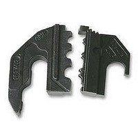
DIE SET, SOLISTRAND
Manufacturer
Tyco Electronics
Series
SOLISTRANDr
Type
Die Setr
Specifications of 169409
Crimp Application
Connectors
Wire Area Size Max
6.6mm2
Wire Area Size Min
0.25mm2
Wire Size Awg Max
10AWG
Wire Size Awg Min
22AWG
Wire Size Swg Max
6
Wire Size Swg Min
29
Product
Crimping, Stripping & Cutting Tools & Drills
Lead Free Status / RoHS Status
na
For Use With
SOLISTRAND Terminals and Splices


3. LOCATOR, STABILIZER, AND DIE ASSEMBLY
When changing dies, first remove the locator and/or
stabilizer and then remove the existing dies before
installing the new dies by performing the following:
3.1. Locator
Loosen each of the locator screws (alternately, one
turn at a time) until the locator can be removed.
3.2. Stabilizer
Remove the stabilizer by removing the stabilizer
screw with the hex wrench supplied with the tool kit.
3.3. Die Removal
3.4. Die Insertion
2 of 3
INSTALLATION AND REMOVAL
1. Remove upper die by positioning the blade tip of
a screwdriver behind and under the die. Push die
outward and apply a rocking action to the die while
pushing it out of the tool frame head. See inset,
Figure 3.
2. Remove lower die by pushing upwards with
thumb and prying out of tool frame using
screwdriver tip.
1. Slide each die into the tool frame head as
shown in Figure 3 until it “clicks” into position.
2. After installing dies, install locator and/ or
stabilizer (as required) according to the instructions
packaged with the die set.
Blade- - Tip
of Screwdriver
(Figure 1)
(Figure 1)
(Figure 3)
(Figure 3)
View from
Rear of
Tool Head
Figure 3
4. CRIMPING PROCEDURE
Refer to the instructions packaged with the die
assemblies for product selection, wire strip lengths,
and correct positioning of product in the crimping
dies. Crimping procedure is as follows:
5. MAINTENANCE/INSPECTION
5.1. Maintenance
NOTE
1. Squeeze tool handles until the ratchet releases
and allow them to open fully.
2. Place the product (terminal, splice, or contact)
into the lower die and squeeze the tool handles
together until the product is held by the dies but the
wire barrel is not deformed.
3. Insert the stripped wire into the wire barrel of the
product.
4. Squeeze the tool handles until the ratchet
releases to complete the crimp.
1. Remove dust, moisture, and other contaminants
with a clean brush, or a clean, soft, lint--free cloth.
Do not use objects that could damage the tool.
2. Make certain that all screws are in place and
secured.
i
In the event that the product is improperly
positioned in the dies, or if the wrong die position
was selected, release the ratchet by squeezing
the tool handles slightly and turning the ratchet
release counterclockwise (see Figure 1). Allow
handles to open and then reposition product
properly.
Typical Dies
(Upper and Lower)
408- 6764
Rev D