PROPER USE GUIDELINES
Cumulative Trauma Disorders can result from the prolonged use of manually powered hand tools. Hand tools are intended for occasional use and low volume
applications. A wide selection of powered application equipment for extended- - use, production operations is available.
1. INTRODUCTION
CERTI--LOK Hand Tool Frame Assembly 169400 is
designed to accept crimping die assemblies which
crimp PIDG* and PLASTI--GRIP* terminals, PIDG
“window” splices, SOLISTRAND* terminals and
splices, and Multimate Type III(+). Refer to the
instructions packaged with the die sets for installation,
selection data, crimping procedure, and die
maintenance.
Documentation for the die sets includes the
instruction sheets listed in Figure 2.
E2011 Tyco Electronics Corporation, a TE Connectivity Ltd. Company
All Rights Reserved
*Trademark
TE Connectivity, TE connectivity (logo), and TE (logo) are trademarks. Other logos, product and/or Company names may be trademarks of their respective owners.
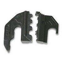
D CAUTION: This die set (169404) is not designed for “red” and “yellow” FASTON* PIDG and PLASTI--GRIP receptacles. Attempts to use
Terminal
Stabilizer
Locator/
Wire Stop
DIE ASSEMBLY PART NUMBER
Ratchet
Release
Lever
these products in this die set will break the stabilizer.
169404
169409
169414
169406
Figure 1
CERTI- LOK* Hand Tool
Frame Assembly 169400
PIDG and PLASTI--GRIP terminals, and PIDG “window” splices
SOLISTRAND terminals and splices
Multimate Type III(+) contacts
Stabilizer
Screw
Ratchet
(Crimp Height)
Adjuster
TOOLING ASSISTANCE CENTER 1--800--722--1111
PRODUCT INFORMATION 1--800--522--6752
Locator
Screws
PRODUCT APPLIED
Figure 2
Reasons for reissue of this sheet are provided in
Section 8, REVISION SUMMARY.
2. DESCRIPTION
The tool features a ratchet, ratchet release lever,
ratchet adjuster, locator/wire stop (hereafter referred
to as “locator”), and a terminal stabilizer (hereafter
referred to as “stabilizer”).
The ratchet release lever enables the tool operator to
open the partially closed tool handles when
necessary. During crimping, the locator correctly
positions wire and product (terminal, splice, or
contact), while the stabilizer (when used) prevents the
product from bending.
The locator and product insulation are color--coded for
a given wire range as listed in the instructions
accompanying the die assembly. The product bearing
the color--coded insulation is crimped in the matching
color--coded crimping closure of the dies.
The ratchet adjuster is used to control the crimp
height of the product’s wire/insulation barrel when a
certain amount of wear has taken place on the ratchet
mechanism or other internal parts of the tool. See
Section 6, RATCHET INSPECTION AND
ADJUSTMENT.
NOTE
NOTE
i
i
Dimensions are in millimeters, with [inches in
brackets]. Figures and illustrations are for
reference only and are not drawn to scale.
The stabilizer and locator are specific to each die
assembly used in the hand tool. When installing
a die assembly, the accompanying stabilizer and
locator must be installed on the tool for proper
functioning.
(Figure 1)
This controlled document is subject to change.
For latest revision and Regional Customer Service,
visit our website at www.te.com
INSTRUCTION SHEET
Instruction Sheet
408--6765D
408- - 6764
07 APR 11
408--6801
408--6858
Rev D
1 of 3
LOC B