ADIS16201CCCZ Analog Devices Inc, ADIS16201CCCZ Datasheet - Page 23
ADIS16201CCCZ
Manufacturer Part Number
ADIS16201CCCZ
Description
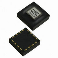
IC ACCELEROMETER LP 16-LGA
Manufacturer
Analog Devices Inc
Datasheet
1.ADIS16201PCBZ.pdf
(32 pages)
Specifications of ADIS16201CCCZ
Acceleration Range
±1.7g
Axis
X, Y
Sensitivity
2.162 LSB/mg
Voltage - Supply
3 V ~ 3.6 V
Output Type
Digital
Bandwidth
2.25kHz
Interface
SPI
Mounting Type
Surface Mount
Package / Case
16-LGA
No. Of Axes
2
Sensor Case Style
LGA
No. Of Pins
16
Supply Voltage Range
3V To 3.6V
Operating Temperature Range
-40°C To +125°C
Msl
MSL 1 - Unlimited
Lead Free Status / RoHS Status
Lead free / RoHS Compliant
For Use With
ADIS16201/PCBZ - BOARD EVAL PCB ADIS16201
Lead Free Status / RoHS Status
Lead free / RoHS Compliant, Lead free / RoHS Compliant
Available stocks
Company
Part Number
Manufacturer
Quantity
Price
Company:

Part Number:
ADIS16201CCCZ
Manufacturer:
IXYS
Quantity:
3 000
Part Number:
ADIS16201CCCZ
Manufacturer:
ADI原装
Quantity:
20 000


ALM_CTRL Register Definition
Address
0x29, 0x28
1
The ALM_CTRL register contains the alarm control variables.
Table 23. ALM_CTRL Bit Designations
Bit
15
14:12
11
10:8
7:3
2
1
0
Default is valid only until the first register write cycle.
Value
000
001
010
011
100
101
110
111
000
001
010
011
100
101
110
111
Default
0x0000
Description
Rate of change (ROC) enable for Alarm 2.
Alarm 2 source selection.
Alarm disable.
Alarm source: power supply output.
Alarm source: X-acceleration output.
Alarm source: Y-acceleration output.
Alarm source: auxiliary ADC output.
Alarm source: temperature sensor output.
Alarm source: X-inclination output.
Alarm source: Y-inclination output.
Rate of change (ROC) enable for Alarm 1.
Alarm 1 source selection.
Alarm disable.
Alarm source: power supply output.
Alarm source: X-acceleration output.
Alarm source: Y-acceleration output.
Alarm source: auxiliary ADC output.
Alarm source: temperature sensor output.
Alarm source: X-inclination output.
Alarm source: Y-inclination output.
Not used.
Alarm output enable.
Alarm output polarity.
Alarm output line select.
1: ROC is active.
0: ROC is inactive.
1: ROC is active.
0: ROC is inactive.
1: Alarm output enabled.
0: Alarm output disabled.
1: Active high.
0: Active low.
1: DIO1.
0: DIO0.
1
Format
N/A
Access
R/W
Rev. A | Page 23 of 32
SAMPLE PERIOD CONTROL
The seven output data variables within the ADIS16201 are
sampled and updated at a rate based upon the SMPL_PRD
control register. The sample period can be precisely controlled
over more than a 3-decade range using a time base with two
settings and a 7-bit binary count. The use of a time base that
varies with a ratio of 1:31 allows for a more optimal resolution
in the sample period than a straight binary counter. This is
reflected in Figure 36, where the frequency is presented on a
logarithmic scale. The choice of the two time base settings
results in making the sample period setting more linear vs. the
logarithmic frequency scale.
Note that the sample period given is defined as the cumulative
time required to sample, process, and update all seven data output
variables. The seven data output variables are sampled as a
group and in unison with one another. Whatever update rate is
selected for one signal, all seven output data variables are updated
at the same rate whether they are monitored via the SPI or not.
For a sample period setting of less than 1098.9 μs (SMPL_RATE ≤
0x07), the overall power dissipation in the part rises by approxi-
mately 300%. The default setting for the SMPL_RATE register is
0x04 at initial power-up, thus allowing for the maximum SPI
clock rate of 2.5 MHz.
256
192
128
64
0
1
Figure 36. SMPL_PRD Values vs. Sample Frequency
10
FREQUENCY (Hz)
100
1k
ADIS16201
10k
Related parts for ADIS16201CCCZ
Image
Part Number
Description
Manufacturer
Datasheet
Request
R

Part Number:
Description:
±1.7g Dual-Axis IMEMS Accelerometer Evaluation Board
Manufacturer:
Analog Devices Inc
Datasheet:

Part Number:
Description:
Inertial Sensor Evaluation System
Manufacturer:
Analog Devices Inc
Datasheet:
Part Number:
Description:
Manufacturer:
Analog Devices Inc
Datasheet:
Part Number:
Description:
Manufacturer:
Analog Devices Inc
Datasheet:
Part Number:
Description:
Manufacturer:
Analog Devices Inc
Datasheet:
Part Number:
Description:
Manufacturer:
Analog Devices Inc
Datasheet:
Part Number:
Description:
Manufacturer:
Analog Devices Inc
Datasheet:
Part Number:
Description:
Manufacturer:
Analog Devices Inc
Datasheet:
Part Number:
Description:
Manufacturer:
Analog Devices Inc
Datasheet:
Part Number:
Description:
Manufacturer:
Analog Devices Inc
Datasheet:
Part Number:
Description:
Manufacturer:
Analog Devices Inc
Datasheet:
Part Number:
Description:
Manufacturer:
Analog Devices Inc
Datasheet:
Part Number:
Description:
Manufacturer:
Analog Devices Inc
Datasheet: