ADIS16201CCCZ Analog Devices Inc, ADIS16201CCCZ Datasheet - Page 13
ADIS16201CCCZ
Manufacturer Part Number
ADIS16201CCCZ
Description
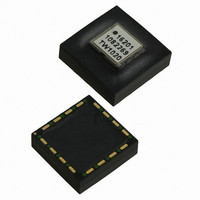
IC ACCELEROMETER LP 16-LGA
Manufacturer
Analog Devices Inc
Datasheet
1.ADIS16201PCBZ.pdf
(32 pages)
Specifications of ADIS16201CCCZ
Acceleration Range
±1.7g
Axis
X, Y
Sensitivity
2.162 LSB/mg
Voltage - Supply
3 V ~ 3.6 V
Output Type
Digital
Bandwidth
2.25kHz
Interface
SPI
Mounting Type
Surface Mount
Package / Case
16-LGA
No. Of Axes
2
Sensor Case Style
LGA
No. Of Pins
16
Supply Voltage Range
3V To 3.6V
Operating Temperature Range
-40°C To +125°C
Msl
MSL 1 - Unlimited
Lead Free Status / RoHS Status
Lead free / RoHS Compliant
For Use With
ADIS16201/PCBZ - BOARD EVAL PCB ADIS16201
Lead Free Status / RoHS Status
Lead free / RoHS Compliant, Lead free / RoHS Compliant
Available stocks
Company
Part Number
Manufacturer
Quantity
Price
Company:

Part Number:
ADIS16201CCCZ
Manufacturer:
IXYS
Quantity:
3 000
Part Number:
ADIS16201CCCZ
Manufacturer:
ADI原装
Quantity:
20 000


THEORY OF OPERATION
The ADIS16201 is a complete dual-axis digital inclinometer/
accelerometer that uses Analog Devices’ surface-micromachining
process and embedded signal processing to make a functionally
complete, low cost dual-axis sensor.
The ADIS16201 offers a fully calibrated, dual–axis
micromachined sensor element that develops independent
analog signals representative of the acceleration levels applied to
the part. An on-board precision ADC samples the acceleration
signals, along with the power supply voltage, an internal
temperature signal, and the auxiliary analog input signal. These
signals are then processed and latched into addressable output
registers. The serial peripheral interface (SPI) provides
convenient, digital access to these registers.
In addition, the acceleration signals are further processed to
produce inclination angle data for both axes. The inclination
angle data represents the tilt away from the ideal plane, which
in this case, is normal to the earth’s gravitational force. This
calculation assumes that no force outside of the earth’s
gravitational force is acting on the device.
ACCELEROMETER OPERATION
The acceleration sensor used in the ADIS16201 is a surface-
machined, polysilicon structure built on top of a silicon wafer.
Polysilicon springs suspend the structure over the surface of the
wafer and provide a resistance against acceleration forces.
Acceleration causes a deflection in the differential capacitor
structure that includes both fixed plates and plates that are
attached to the moving mass. The fixed plates are driven by a set
of square waves that are 180
Acceleration deflects the beam and unbalances the differential
capacitor, resulting in an output square wave whose amplitude
is proportional to acceleration. Phase sensitive demodulation
techniques rectify the signal and determine the direction of the
acceleration. The output of the demodulator is amplified,
digitized, and processed to remove any process variations and
sensitivities to supply variations.
INCLINOMETER OPERATION
The ADIS16201 inclinometer output data is linear with respect
to degrees of inclination and is dependent on no forces, other
than gravity, acting on the device. The ADIS16201 leverages a
simple geometrical relationship to convert its calibrated
acceleration measurements into an accurate inclination angle
estimate. Figure 31 displays the acceleration measurements
associated with each incline angle, along with the resulting
inclination angle estimate produced by the ADIS16201.
o
out-of-phase from one another.
Rev. A | Page 13 of 32
One important behavior to observe when using this approach is
the fact that the relationship between the acceleration
measurements and inclination angle is nonlinear. This non-
linear behavior results in larger quantization error changes as
the inclination angle approaches 90°. Figure 32 provides a closer
look at this behavior by illustrating the increase in step size as
the inclination angle estimate increases. Figure 33 offers a direct
relationship between the quantization error and the overall
inclination angle.
Figure 31. Acceleration and Inclination Angle vs. Actual Tilt Angle
Figure 32. Acceleration and Inclination Angle vs. Actual Tilt Angle
75
0
22.5
INCLINATION
80
TILT (Degrees)
TILT (Degrees)
INCLINATION
45.0
ACCELERATION
ACCELERATION
85
67.5
ADIS16201
90.0
90
Related parts for ADIS16201CCCZ
Image
Part Number
Description
Manufacturer
Datasheet
Request
R

Part Number:
Description:
±1.7g Dual-Axis IMEMS Accelerometer Evaluation Board
Manufacturer:
Analog Devices Inc
Datasheet:

Part Number:
Description:
Inertial Sensor Evaluation System
Manufacturer:
Analog Devices Inc
Datasheet:
Part Number:
Description:
Manufacturer:
Analog Devices Inc
Datasheet:
Part Number:
Description:
Manufacturer:
Analog Devices Inc
Datasheet:
Part Number:
Description:
Manufacturer:
Analog Devices Inc
Datasheet:
Part Number:
Description:
Manufacturer:
Analog Devices Inc
Datasheet:
Part Number:
Description:
Manufacturer:
Analog Devices Inc
Datasheet:
Part Number:
Description:
Manufacturer:
Analog Devices Inc
Datasheet:
Part Number:
Description:
Manufacturer:
Analog Devices Inc
Datasheet:
Part Number:
Description:
Manufacturer:
Analog Devices Inc
Datasheet:
Part Number:
Description:
Manufacturer:
Analog Devices Inc
Datasheet:
Part Number:
Description:
Manufacturer:
Analog Devices Inc
Datasheet:
Part Number:
Description:
Manufacturer:
Analog Devices Inc
Datasheet: