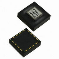
ADIS16201CCCZ Analog Devices Inc, ADIS16201CCCZ Datasheet - Page 22

ADIS16201CCCZ
Manufacturer Part Number
ADIS16201CCCZ
Description
IC ACCELEROMETER LP 16-LGA
Manufacturer
Analog Devices Inc
Datasheet
1.ADIS16201PCBZ.pdf
(32 pages)
Specifications of ADIS16201CCCZ
Acceleration Range
±1.7g
Axis
X, Y
Sensitivity
2.162 LSB/mg
Voltage - Supply
3 V ~ 3.6 V
Output Type
Digital
Bandwidth
2.25kHz
Interface
SPI
Mounting Type
Surface Mount
Package / Case
16-LGA
No. Of Axes
2
Sensor Case Style
LGA
No. Of Pins
16
Supply Voltage Range
3V To 3.6V
Operating Temperature Range
-40°C To +125°C
Msl
MSL 1 - Unlimited
Lead Free Status / RoHS Status
Lead free / RoHS Compliant
For Use With
ADIS16201/PCBZ - BOARD EVAL PCB ADIS16201
Lead Free Status / RoHS Status
Lead free / RoHS Compliant, Lead free / RoHS Compliant
Available stocks
Company
Part Number
Manufacturer
Quantity
Price
Company:
Part Number:
ADIS16201CCCZ
Manufacturer:
IXYS
Quantity:
3 000
Part Number:
ADIS16201CCCZ
Manufacturer:
ADI原装
Quantity:
20 000
ADIS16201
The versatility built into the alarm function is intended to allow
the user to adapt to a number of different applications. For
example, in the case of monitoring a twos complement variable,
the GT1 bit within the ALM_MAG1 control register can allow
for the detection of negative excursions below a fixed level. In
addition, the Alarm 1 and Alarm 2 functions can be set to
monitor the same variable that allows the user to discern if an
output variable remains within a predefined window.
Other options include the ROC function that can be used in
monitoring high frequency shock levels in the acceleration
outputs or slowly changing outputs in the inclination level over
a period of a minute or more. With the addition of the alarm
hardware functionality, the ADIS16201 can be left to run
independently of the main processor and interrupt the system
only when an alarm condition occurs. Conversely, the alarm
condition can be monitored through the routine polling of any
one of the seven data output registers.
Note that the alarm functions work from instantaneous data
and not averaged data that can be present when the AVG_CNT
register is not set to 0. The alarm hardware output indicator is
not latched but tracks the actual alarm conditions in real time.
ALM_MAG1 Register Definition
Address
0x21, 0x20
1
The ALM_MAG1 register contains the threshold level for
Alarm 1. The contents of this register are nonvolatile.
Table 19. ALM_MAG1 Bit Designations
Bit
15
14
13:0
ALM_SMPL1 Register Definition
Address
0x25, 0x24
1
Default is valid only until the first register write cycle.
Default is valid only until the first register write cycle.
Description
Greater than active alarm bit.
Not used.
Data bits. This number can be either twos
complement or straight binary. The format is set by
the value being monitored by this function.
1: Alarm is active for an output greater than Alarm
Magnitude 1 register setting.
0: Alarm is active for an output less than Alarm
Magnitude 1 register setting.
Default
0x0000
Default
0x0000
1
1
Format
N/A
Format
Binary
Access
Access
R/W
R/W
Rev. A | Page 22 of 32
The ALM_SMPL1 register contains the sample period
information for Alarm 1, when it is set for rate-of-change alarm
monitoring. The rate-of-change alarm function averages the
change in the output variable over the specified number of
samples and compares this change directly to the values
specified in the ALM_MAG1 register. The contents of this
register are nonvolatile.
Table 20. ALM_SMPL1 Bit Designations
Bit
15:8
7:0
ALM_MAG2 Register Definition
Address
0x23, 0x22
1
The ALM_MAG2 register contains the threshold level for
Alarm 2. The contents of this register are nonvolatile.
Table 21. ALM_MAG2 Bit Designations
Bit
15
14
13:0
ALM_SMPL2 Register Definition
Address
0x27, 0x26
1
The ALM_SMPL2 register contains the sample period
information for Alarm 2, when it is set for rate-of-change alarm
monitoring. The rate-of-change alarm function averages the
change in the output variable over the specified number of
samples and compares this change directly to the values
specified in the ALM_MAG1 register. The contents of this
register are nonvolatile.
Table 22. ALM_SMPL2 Bit Designations
Bit
15:8
7:0
Default is valid only until the first register write cycle.
Default is valid only until the first register write cycle.
Description
Not used
Data bits
Description
Greater than active alarm bit.
Not used.
Data bits. This number can be either twos
complement or straight binary. The format is set by
the value being monitored by this function.
Description
Not used
Data bits
1: Alarm is active for an output greater than Alarm
Magnitude 2 register setting.
0: Alarm is active for an output less than Alarm
Magnitude 2 register setting.
Default
0x0000
Default
0x0000
1
1
Format
N/A
Format
Binary
Access
R/W
Access
R/W


