ADP3212MNR2G ON Semiconductor, ADP3212MNR2G Datasheet - Page 9
ADP3212MNR2G
Manufacturer Part Number
ADP3212MNR2G
Description
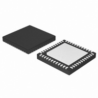
IC CTLR BUCK 7BIT 2PHASE 48QFN
Manufacturer
ON Semiconductor
Datasheet
1.NCP3218MNR2G.pdf
(35 pages)
Specifications of ADP3212MNR2G
Applications
Controller, Intel IMVP-6.5™
Voltage - Input
3.3 V ~ 22 V
Number Of Outputs
1
Voltage - Output
0.3 V ~ 1.5V
Operating Temperature
-40°C ~ 100°C
Mounting Type
Surface Mount
Package / Case
48-TFQFN Exposed Pad
Output Voltage
0.9512 V
Output Current
52 A
Input Voltage
8 V to 19 V
Supply Current
7 mA
Switching Frequency
300 KHz
Mounting Style
SMD/SMT
Maximum Operating Temperature
+ 100 C
Minimum Operating Temperature
- 40 C
Lead Free Status / RoHS Status
Lead free / RoHS Compliant
Available stocks
Company
Part Number
Manufacturer
Quantity
Price
Company:

Part Number:
ADP3212MNR2G
Manufacturer:
ON Semiconductor
Quantity:
950
Part Number:
ADP3212MNR2G
Manufacturer:
ON/安森美
Quantity:
20 000


ELECTRICAL CHARACTERISTICS
V
V
SUPPLY
HIGH−SIDE MOSFET DRIVER
LOW−SIDE MOSFET DRIVER
BOOTSTRAP RECTIFIER SWITCH
1. All limits at temperature extremes are guaranteed via correlation using standard statistical quality control (SQC).
2. Guaranteed by design or bench characterization, not production tested.
3. Based on bench characterization data.
4. Timing is referenced to the 90% and 10% points, unless otherwise noted.
VCC Hysteresis (Note 2)
Pullup Resistance, Sourcing
Current (Note 3)
Pulldown Resistance, Sinking
Current (Note 3)
Transition Times
Dead Delay Times
BST Quiescent Current
Pullup Resistance, Sourcing
Current (Note 3)
Pulldown Resistance, Sinking
Current (Note 3)
Transition Times
Propagation Delay Times
SW Transition Timeout
SW Off Threshold
PVCC Quiescent Current
On Resistance (Note 3)
(WITH RESPECT TO SW)
CC
VID
= PV
= V
DAC
CC
DRVH
DRVL
Parameter
= 5.0 V, FBRTN = PGND = GND = 0 V, H = 5.0 V, L = 0 V, EN = VARFREQ = H, DPRSLP = L, PSI = 1.05 V,
= 1.2000 V, T
SW
A
= −40°C to 100°C, unless otherwise noted. (Note 1) Current entering a pin (sink current) has a positive sign.
tpdh
tpdh
tpdh
DRVH
Symbol
V
tr
tf
tr
tf
t
OFFSW
TOSW
DRVH
DRVH
DRVL
DRVL
DRVH
DRVL
Figure 2. Timing Diagram
tf
DRVL
BST = PVCC
BST = PVCC
BST = PVCC, C
BST = PVCC, C
BST = PVCC, Figure 2
EN = L (Shutdown)
EN = H, no switching
C
C
C
DRVH = L, SW = 2.5 V
EN = L (Shutdown)
EN = H, no switching
EN = L or EN = H and DRVL = H
http://onsemi.com
L
L
L
= 3 nF, Figure 2
= 3 nF, Figure 2
= 3 nF, Figure 2
V
TH
tr
9
DRVH
Conditions
L
L
= 3 nF, Figure 2
= 3 nF, Figure 2
(Note 4)
V
TH
1.0 V
Min
100
4.0
15
tpdh
tf
DRVH
tr
Typ
150
200
250
170
1.8
1.0
1.0
1.7
0.8
2.5
1.0
6.0
15
13
30
15
14
11
DRVL
DRVL
Max
350
3.3
2.0
2.8
1.7
8.0
30
25
40
10
35
35
30
10
Units
mV
mA
mA
ns
ns
ns
ns
ns
W
W
W
W
W
V
Related parts for ADP3212MNR2G
Image
Part Number
Description
Manufacturer
Datasheet
Request
R

Part Number:
Description:
7-bit Programmable, 3-phase,mobile Cpu Synchronous Buck Controller
Manufacturer:
ON Semiconductor
Datasheet:


Part Number:
Description:
Programming Socket Adapters & Emulators EEROM-8U ADAPTER 32-PIN PLCC PACKAGE
Manufacturer:
EETools
Datasheet:
Part Number:
Description:
ON Semiconductor [VOLTAGE REGULATOR]
Manufacturer:
ON Semiconductor
Datasheet:
Part Number:
Description:
357-036-542-201 CARDEDGE 36POS DL .156 BLK LOPRO
Manufacturer:
ON Semiconductor
Datasheet:
Part Number:
Description:
357-036-542-201 CARDEDGE 36POS DL .156 BLK LOPRO
Manufacturer:
ON Semiconductor
Datasheet:
Part Number:
Description:
357-036-542-201 CARDEDGE 36POS DL .156 BLK LOPRO
Manufacturer:
ON Semiconductor
Datasheet:
Part Number:
Description:
357-036-542-201 CARDEDGE 36POS DL .156 BLK LOPRO
Manufacturer:
ON Semiconductor
Datasheet:
Part Number:
Description:
357-036-542-201 CARDEDGE 36POS DL .156 BLK LOPRO
Manufacturer:
ON Semiconductor
Datasheet:
Part Number:
Description:
357-036-542-201 CARDEDGE 36POS DL .156 BLK LOPRO
Manufacturer:
ON Semiconductor
Datasheet:
Part Number:
Description:
357-036-542-201 CARDEDGE 36POS DL .156 BLK LOPRO
Manufacturer:
ON Semiconductor
Datasheet:
Part Number:
Description:
357-036-542-201 CARDEDGE 36POS DL .156 BLK LOPRO
Manufacturer:
ON Semiconductor
Datasheet:
Part Number:
Description:
357-036-542-201 CARDEDGE 36POS DL .156 BLK LOPRO
Manufacturer:
ON Semiconductor
Datasheet:
Part Number:
Description:
357-036-542-201 CARDEDGE 36POS DL .156 BLK LOPRO
Manufacturer:
ON Semiconductor
Datasheet: