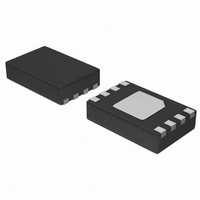
CAT34TS02VP2GT4B ON Semiconductor, CAT34TS02VP2GT4B Datasheet - Page 8

CAT34TS02VP2GT4B
Manufacturer Part Number
CAT34TS02VP2GT4B
Description
IC TEMP SENSOR 2KB MEM 8-TDFN
Manufacturer
ON Semiconductor
Datasheet
1.CAT34TS02VP2GT4A.pdf
(22 pages)
Specifications of CAT34TS02VP2GT4B
Function
Temp Monitoring System (Sensor)
Topology
ADC (Sigma Delta), Comparator, Register Bank
Sensor Type
Internal
Sensing Temperature
-40°C ~ 125°C
Output Type
I²C™, SPI™
Output Alarm
Yes
Output Fan
No
Voltage - Supply
2.97 V ~ 3.63 V
Operating Temperature
-40°C ~ 125°C
Mounting Type
Surface Mount
Package / Case
8-WFDFN Exposed Pad
Digital Output - Bus Interface
I2C, SMBus
Digital Output - Number Of Bits
12 bit
Supply Voltage (min)
3.3 V
Description/function
Digital Output Temperature Sensor with On-board SPD EEPROM
Maximum Operating Temperature
+ 130 C
Minimum Operating Temperature
- 45 C
Supply Current
500 uA
Lead Free Status / RoHS Status
Lead free / RoHS Compliant
Available stocks
Company
Part Number
Manufacturer
Quantity
Price
Company:
Part Number:
CAT34TS02VP2GT4B
Manufacturer:
ON Semiconductor
Quantity:
2 900
Part Number:
CAT34TS02VP2GT4B
Manufacturer:
ON/安森美
Quantity:
20 000
CAT34TS02
WRITE OPERATIONS
EEPROM Byte and TS Register Write
To write data to a TS register, or to the on-board
EEPROM, the Master creates a START condition on
the bus, and then sends out the appropriate Slave
address (with the R/W ¯ ¯ bit set to ‘0’), followed by an
address byte and data byte(s). The matching Slave
will acknowledge the Slave address, EEPROM byte
or TS register address and the data byte(s), one for
EEPROM data (Figure 5) and two for TS register
data (Figure 6). The Master then ends the session
by creating a STOP condition on the bus. The STOP
completes the (volatile) TS register update or starts
the internal Write cycle for the (non-volatle)
EEPROM data (Figure 7).
EEPROM Page Write
The on-board EEPROM contains 256 bytes of data,
arranged in 16 pages of 16 bytes each. A page is
selected by the 4 most significant bits of the address
byte immediatelly following the Slave address, while
the 4 least significant bits point to the byte within the
page. Up to 16 bytes can be written in one Write
cycle (Figure 8).
The internal EEPROM byte address counter is
automatically incremented after each data byte is
loaded. If the Master transmits more than 16 data
bytes, then earlier data will be overwritten by later
data in a ‘wrap-around’ fashion within the selected
page. The internal Write cycle, using the most
recently loaded data, then starts immediatelly
following the STOP.
Acknowledge Polling
Acknowledge polling can be used to determine if the
CAT34TS02 is busy writing to EEPROM, or is ready
to accept commands. Polling is executed by
interrogating the device with a ‘Selective Read’
command
(see
READ
OPERATIONS).
The
CAT34TS02 will not acknowlwdge the Slave
address as long as internal EEPROM Write is in
progress.
DELIVERY STATE
The CAT34TS02 is shipped ‘unprotected’, i.e. neither
Software Write Protection (SWP) flag is set. The
entire 2-Kb memory is erased, i.e. all bytes are 0xFF.
8
Doc. No. MD-1129 Rev. H
© 2010 SCILLC. All rights reserved.
Characteristics subject to change without notice


