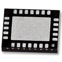
LM25066APSQE/NOPB National Semiconductor, LM25066APSQE/NOPB Datasheet - Page 34

LM25066APSQE/NOPB
Manufacturer Part Number
LM25066APSQE/NOPB
Description
IC CTLR PM HOTSWAP 24-LLP
Manufacturer
National Semiconductor
Series
PowerWise®r
Specifications of LM25066APSQE/NOPB
Applications
Base Station-Networking Line Cards, Servers
Current - Supply
5.8mA
Voltage - Supply
2.9 V ~ 17 V
Operating Temperature
-40°C ~ 85°C
Mounting Type
*
Package / Case
*
Input Voltage
17V
Internal Switch
No
Supply Voltage Range
2.9V To 5.5V
Rohs Compliant
Yes
Digital Ic Case Style
LLP
No. Of Pins
24
Lead Free Status / RoHS Status
Lead free / RoHS Compliant
Other names
LM25066APSQE/NOPBTR
www.national.com
Manufacturer Specific PMBus™
Commands
MFR_SPECIFIC_00: READ_VAUX (D0h)
The READ_VAUX command will report the 12-bit ADC mea-
sured auxiliary voltage. Voltages greater than or equal to
1.16V to ground will be reported at plus full scale (0FFFh).
Voltages less than or equal to 0V referenced to ground will be
reported as 0 (0000h). Coefficients for the VAUX value are
dependent on the value of the external divider (if used). To
read data from the MFR_READ_VAUX command, use the
PMBus™ Read Word protocol.
MFR_SPECIFIC_01: MFR_READ_IIN (D1h)
The MFR_READ_IIN command will report the 12-bit ADC
measured current sense voltage. To read data from the
MFR_READ_IIN command, use the PMBus™ Read Word
protocol. Reading this register should use the coefficients
shown in the Telemetry and Warning Conversion Coefficients
Table. Please see the section on coefficient calculations to
calculate the values to use.
MFR_SPECIFIC_02: MFR_READ_PIN (D2h)
The MFR_READ_PIN command will report the upper 12 bits
of the VIN x IIN product as measured by the 12-bit ADC. To
read data from the MFR_READ_PIN command, use the PM-
Bus™ Read Word protocol. Reading this register should use
the coefficients shown in the Telemetry and Warning Con-
version Coefficients Table. Please see the section on coeffi-
cient calculations to calculate the values to use.
MFR_SPECIFIC_03: MFR_IN_OC_WARN_LIMIT (D3h)
The MFR_IIN_OC_WARN_LIMIT PMBus™ command sets
the input over-current warning threshold. In the event that the
input current rises above the value set in this register, the IIN
Over-current flags are set in the status registers and the SM-
BA is asserted. To access the MFR_IIN_OC_WARN_LIMIT
register, use the PMBus™ Read/Write Word protocol. Read-
ing/writing to this register should use the coefficients shown
in the Telemetry and Warning Conversion Coefficients Table.
Value
0h – 0FFFh
Value
0h – 0FFFh
Value
0h – 0FFFh
TABLE 22. MFR_READ_VAUX Register
TABLE 24. MFR_READ_PIN Register
TABLE 23. MFR_READ_IIN Register
Meaning
Measured value
for VAUX input
Meaning
Measured value
for input current
sense voltage
Meaning
Value for input
current x input
voltage
Default
0000h
Default
0000h
Default
0000h
34
MFR_SPECIFIC_04: MFR_PIN_OP_WARN_LIMIT (D4h)
The MFR_PIN_OP_WARN_LIMIT PMBus™ command sets
the input over-power warning threshold. In the event that the
input power rises above the value set in this register, the PIN
Over-power flags are set in the status registers and the SM-
BA is asserted. To access the MFR_PIN_OP_WARN_LIMIT
register, use the PMBus™ Read/Write Word protocol. Read-
ing/writing to this register should use the coefficients shown
in the Telemetry and Warning Conversion Coefficients Table.
MFR_SPECIFIC_05: READ_PIN_PEAK (D5h)
The READ_PIN_PEAK command will report the maximum
input power measured since a Power On reset or the last
CLEAR_PIN_PEAK
READ_PIN_PEAK command, use the PMBus™ Read Word
protocol. Use the coefficients shown in the Telemetry and
Warning Coefficients Table.
MFR_SPECIFIC_06: CLEAR_PIN_PEAK (D6h)
The CLEAR_PIN_PEAK command will clear the PIN_PEAK
register. This command uses the PMBus™ Send Byte proto-
col.
MFR_SPECIFIC_07: GATE_MASK (D7h)
The GATE_MASK register allows the hardware to prevent
fault conditions from switching off the MOSFET. When the bit
is high, the corresponding FAULT has no control over the
MOSFET gate. All status registers will still be updated (STA-
TUS, DIAGNOSTIC) and an SMBA will still be issued. This
register is accessed with the PMBus™ Read / Write Byte pro-
tocol.
Warning: Inhibiting the MOSFET switch off in response to over-cur-
Value
0h – 0FFEh
0FFFh
Value
0h – 0FFEh
0FFFh
Value
0h – 0FFEh
TABLE 26. MFR_PIN_OP_WARN_LIMIT Register
TABLE 25. MFR_IIN_OC_WARN_LIMIT Register
rent or circuit breaker fault conditions will likely result in
the destruction of the MOSFET! This functionality should
be used with great care and supervision!
TABLE 27. READ_PIN_PEAK Register
Meaning
Value for input
over-current warn
limit
Input over-current
warning disabled
Meaning
Value for input
over-power warn
limit
Input over-power
warning disabled
Meaning
Maximum Value
for input current x
input voltage since
reset or last clear
command.
To
Default
0FFFh
n/a
Default
0FFFh
n/a
Default
0h
access
the


