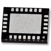
LM25066APSQE/NOPB National Semiconductor, LM25066APSQE/NOPB Datasheet - Page 29

LM25066APSQE/NOPB
Manufacturer Part Number
LM25066APSQE/NOPB
Description
IC CTLR PM HOTSWAP 24-LLP
Manufacturer
National Semiconductor
Series
PowerWise®r
Specifications of LM25066APSQE/NOPB
Applications
Base Station-Networking Line Cards, Servers
Current - Supply
5.8mA
Voltage - Supply
2.9 V ~ 17 V
Operating Temperature
-40°C ~ 85°C
Mounting Type
*
Package / Case
*
Input Voltage
17V
Internal Switch
No
Supply Voltage Range
2.9V To 5.5V
Rohs Compliant
Yes
Digital Ic Case Style
LLP
No. Of Pins
24
Lead Free Status / RoHS Status
Lead free / RoHS Compliant
Other names
LM25066APSQE/NOPBTR
STANDARD PMBus™ COMMANDS
OPERATION (01h)
The OPERATION command is a standard PMBus ™ com-
mand that controls the MOSFET switch. This command may
be used to switch the MOSFET ON and OFF under host con-
trol. It is also used to re-enable the MOSFET after a fault
triggered shutdown. It is also used to re-enable the MOSFET
after a fault triggered shutdown. Writing only an ON command
after a fault triggered shutdown will not clear the fault regis-
ters. The host must clear the fault condition prior to re-en-
abling the MOSFET in this situation. The OPERATION
command is issued with the write byte protocol.
CLEAR FAULTS (03h)
The CLEAR_FAULTS command is a standard PMBus ™
command that resets all stored warning and fault flags and
the SMBA signal. If a fault or warning condition still exists
when the CLEAR_FAULTS command is issued, the SMBA
signal may not clear or will re-assert almost immediately. Is-
suing a CLEAR_FAULTS command will not cause the MOS-
FET to switch back on in the event of a fault turn-off: that must
be done by issuing an OPERATION command after the fault
condition is cleared. This command uses the PMBus ™ send
byte protocol.
CAPABILITY (19h)
The CAPABILITY command is a standard PMBus ™ com-
mand that returns information about the PMBus ™ functions
supported by the LM25066A. This command is read with the
PMBus ™ read byte protocol.
VOUT_UV_WARN_LIMIT (58h)
The VOUT_UV_WARN_LIMIT command is a standard PM-
Bus ™ command that allows configuring or reading the thresh-
old for the VOUT Under-voltage Warning detection. Reading
and writing to this register should use the coefficients shown
in the Telemetry and Warning Conversion Coefficients Table.
Accesses to this command should use the PMBus ™ read or
write word protocol. If the measured value of VOUT falls be-
low the value in this register, VOUT UV Warn flags are set in
the respective registers, and the SMBA signal is asserted.
Value
80h
00h
Value Meaning
B0h
Value
1h – 0FFFh
0000h
TABLE 2. Recognized OPERATION Command Values
TABLE 4. VOUT_UV_WARN_LIMIT Register
Supports Packet Error Check, 400Kbits/
sec, Supports SMBus Alert
TABLE 3. CAPABILITY Register
Meaning
Switch ON
Switch OFF
Meaning
VOUT Under-
voltage Warning
detection
threshold
VOUT Under-
voltage Warning
disabled
Default
0000h (disabled)
n/a
Default
80h
n/a
Default
B0h
29
OT_FAULT_LIMIT (4Fh)
The OT_FAULT_LIMIT command is a standard PMBus ™
command that allows configuring or reading the threshold for
the over-temperature fault detection. Reading and writing to
this register should use the coefficients shown in the Teleme-
try and Warning Conversion Coefficients Table. Accesses to
this command should use the PMBus ™ read or write word
protocol. If the measured temperature exceeds this value, an
over-temperature fault is triggered, the MOSFET is switched
off, OT Fault flags are set in the respective registers, and the
SMBA signal is asserted. After the measured temperature
falls below the value in this register, the MOSFET may be
switched back on with the OPERATION command. A single
temperature measurement is an average of 16 round-robin
cycles. Therefore, the minimum temperature fault detection
time is 16 ms.
OT_WARN_LIMIT (51h)
The OT_WARN_LIMIT command is a standard PMBus ™
command that allows configuring or reading the threshold for
the over-temperature warning detection. Reading and writing
to this register should use the coefficients shown in the
Telemetry and Warning Conversion Coefficients Table. Ac-
cesses to this command should use the PMBus ™ read or
write word protocol. If the measured temperature exceeds this
value, an over-temperature warning is triggered, the OT
Warning flags set in the respective registers, and the SMBA
signal is asserted. A single temperature measurement is an
average of 16 round-robin cycles. Therefore, the minimum
temperature fault detection time is 16 ms.
VIN_OV_WARN_LIMIT (57h)
The VIN_OV_WARN_LIMIT command is a standard PM-
Bus ™ command that allows configuring or reading the thresh-
old for the VIN over-voltage warning detection. Reading and
writing to this register should use the coefficients shown in the
Telemetry and Warning Conversion Coefficients Table. Ac-
cesses to this command should use the PMBus ™ read or
write word protocol. If the measured value of VIN rises above
the value in this register, VIN OV Warn flags are set in the
respective registers, and the SMBA signal is asserted.
Value
0h – 0FFEh
0FFFh
Value
0h – 0FFEh
0FFFh
TABLE 5. OT_FAULT_LIMIT Register
TABLE 6. OT_WARN_LIMIT Register
Meaning
Over-temperature
Fault threshold
value
Over-temperature
Fault detection
disabled
Meaning
Over-temperature
Warn Threshold
Value
Over-temperature
Warn detection
disabled
Default
0960h (150°C)
n/a
Default
07D0h (125°C)
n/a
www.national.com


