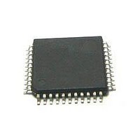
MC56F8255VLD Freescale Semiconductor, MC56F8255VLD Datasheet - Page 70

MC56F8255VLD
Manufacturer Part Number
MC56F8255VLD
Description
DSC 64K FLASH 60MHZ 44-LQFP
Manufacturer
Freescale Semiconductor
Series
56F8xxxr
Datasheets
1.TWR-56F8257.pdf
(88 pages)
2.MC56F8245VLD.pdf
(14 pages)
3.MC56F8245VLD.pdf
(2 pages)
4.MC56F8245VLD.pdf
(629 pages)
Specifications of MC56F8255VLD
Core Processor
56800E
Core Size
16-Bit
Speed
60MHz
Connectivity
CAN, I²C, LIN, SCI, SPI
Peripherals
LVD, POR, PWM, WDT
Number Of I /o
35
Program Memory Size
64KB (32K x 16)
Program Memory Type
FLASH
Ram Size
4K x 16
Voltage - Supply (vcc/vdd)
3 V ~ 3.6 V
Data Converters
A/D 8x12b, D/A 1x12b
Oscillator Type
Internal
Operating Temperature
-40°C ~ 105°C
Package / Case
44-LQFP
Product
DSCs
Processor Series
56800E
Core
56800E
Device Million Instructions Per Second
60 MIPs
Maximum Clock Frequency
60 MHz
Number Of Programmable I/os
35
Data Ram Size
8 KB
Operating Supply Voltage
3.3 V
Maximum Operating Temperature
+ 105 C
Mounting Style
SMD/SMT
Minimum Operating Temperature
- 40 C
On-chip Adc
12 bit, 4 Channel
Lead Free Status / RoHS Status
Lead free / RoHS Compliant
Eeprom Size
-
Lead Free Status / Rohs Status
Details
Available stocks
Company
Part Number
Manufacturer
Quantity
Price
Company:
Part Number:
MC56F8255VLD
Manufacturer:
Freescale Semiconductor
Quantity:
10 000
Specifications
7.26 Digital-to-Analog Converter (DAC) Parameters
70
DC Specifications
Resolution
Settling time
Power-up time
Accuracy
Integral non-linearity
Differential non-linearity
Monotonicity
Offset error
Gain error
DAC Output
Output voltage range
AC Specifications
Signal-to-noise ratio
Spurious free dynamic
range
Effective number of bits
2.
3.
4.
5.
Parasitic capacitance due to the chip bond pad, ESD protection devices, and signal routing: 2.04 pF
8 pF noise damping capacitor
Sampling capacitor at the sample and hold circuit. Capacitor C1 is normally disconnected from the input and is only
connected to it at sampling time: C
S1 and S2 switch phases are non-overlapping and operate at the ADC clock frequency.
Parameter
1
1
1
1
At output load
R
C
Time from release of PWRDWN
signal until DACOUT signal is
valid
Range of input digital words:
410 to 3891 ($19A - $F33)
5% to 95% of full range
Range of input digital words:
410 to 3891 ($19A - $F33)
5% to 95% of full range
> 6 sigma monotonicity,
< 3.4 ppm non-monotonicity
Range of input digital words:
410 to 3891 ($19A - $F33)
5% to 95% of full range
Range of input digital words:
410 to 3891 ($19A - $F33)
5% to 95% of full range
Within 40 mV of either V
V
REFHX
LD
LD
MC56F825x/MC56F824x Digital Signal Controller, Rev. 3
Conditions/Comments
= 3 K
= 400 pf
Figure 31. Equivalent Circuit for A/D Loading
S 1
S 2
gain
Table 42. DAC Parameters
= 1.4 pF for x1 gain, 2.8 pF for x2 gain, and 5.6 pF for x4 gain.
REFLX
or
V
Symbol
ENOB
SFDR
E
t
OFFSET
V
SNR
DAPU
DNL
INL
GAIN
OUT
V
+0.04V
TBD
REFLX
Min
12
—
—
—
—
—
—
—
—
guaranteed
+/- 0.8
+/- 25
+/- .5
+/- 3
TBD
TBD
Typ
—
—
—
—
—
Freescale Semiconductor
V
- 0.04V
+/- 8.0
+/- 1.0
+/- 1.5
+/- 40
REFHX
Max
12
11
—
—
—
2
LSB
LSB
Unit
bits
Bits
mV
µS
µS
dB
dB
—
%
V
2
2


