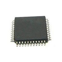
MC56F8255VLD Freescale Semiconductor, MC56F8255VLD Datasheet - Page 56

MC56F8255VLD
Manufacturer Part Number
MC56F8255VLD
Description
DSC 64K FLASH 60MHZ 44-LQFP
Manufacturer
Freescale Semiconductor
Series
56F8xxxr
Datasheets
1.TWR-56F8257.pdf
(88 pages)
2.MC56F8245VLD.pdf
(14 pages)
3.MC56F8245VLD.pdf
(2 pages)
4.MC56F8245VLD.pdf
(629 pages)
Specifications of MC56F8255VLD
Core Processor
56800E
Core Size
16-Bit
Speed
60MHz
Connectivity
CAN, I²C, LIN, SCI, SPI
Peripherals
LVD, POR, PWM, WDT
Number Of I /o
35
Program Memory Size
64KB (32K x 16)
Program Memory Type
FLASH
Ram Size
4K x 16
Voltage - Supply (vcc/vdd)
3 V ~ 3.6 V
Data Converters
A/D 8x12b, D/A 1x12b
Oscillator Type
Internal
Operating Temperature
-40°C ~ 105°C
Package / Case
44-LQFP
Product
DSCs
Processor Series
56800E
Core
56800E
Device Million Instructions Per Second
60 MIPs
Maximum Clock Frequency
60 MHz
Number Of Programmable I/os
35
Data Ram Size
8 KB
Operating Supply Voltage
3.3 V
Maximum Operating Temperature
+ 105 C
Mounting Style
SMD/SMT
Minimum Operating Temperature
- 40 C
On-chip Adc
12 bit, 4 Channel
Lead Free Status / RoHS Status
Lead free / RoHS Compliant
Eeprom Size
-
Lead Free Status / Rohs Status
Details
Available stocks
Company
Part Number
Manufacturer
Quantity
Price
Company:
Part Number:
MC56F8255VLD
Manufacturer:
Freescale Semiconductor
Quantity:
10 000
Specifications
7.8
7.9
The MC56F825x/MC56F824x has two on-chip regulators. One supplies the PLL, crystal oscillator, NanoEdge placement
PWM, and relaxation oscillator. It has no external pins and therefore has no external characteristics that must be guaranteed
(other than proper operation of the device). The second regulator supplies approximately 2.5 V to the
MC56F825x/MC56F824x’s core logic. For proper operation, this regulator requires an external capacitor of 2.2 µF or greater.
Ceramic and tantalum capacitors tend to provide better performance tolerances. The output voltage can be measured directly
on the V
7.10
Tests are conducted using the input levels specified in
from the 50% to the 50% point, and rise and fall times are measured between the 10% and 90% points, as shown in
56
CAP
Input Signal
1
2
3
4
Power-On Reset, Low Voltage Detection Specification
Voltage Regulator Specifications
AC Electrical Characteristics
Low-Voltage Interrupt for 3.3 V supply
Low-Voltage Interrupt for 2.5 V supply
Low-Voltage Interrupt Recovery Hysteresis
Power-On Reset Threshold
Brown-Out Reset Threshold
(V
pin. The specifications for this regulator appear in
Brown-Out Reset occurs whenever the internally regulated 2.5 V digital supply drops below 1.8 V.
When V
When V
While power is ramping up, this signal remains active for as long as the internal 2.5 V is below 2.18 V or
the 3.3 V V
voltage is typically 100 mV less than V
ulates.
Short Circuit Tolerance
Short Circuit Current
CAP
Characteristic
shorted to ground)
DD
DD
drops below LVI27, an interrupt is generated.
drops below LVI21, an interrupt is generated.
DD
Table 25. Power-On Reset and Low-Voltage Detection Parameters
Characteristic
voltage is below 2.7 V, no matter how long the ramp-up rate is. The internally regulated
Fall Time
Midpoint1
MC56F825x/MC56F824x Digital Signal Controller, Rev. 3
Figure 15. Input Signal Measurement References
V
3
IH
4
Table 26. Regulator Parameters
The midpoint is V
DD
1
2
Symbol
T
during ramp-up until 2.5 V is reached, at which time it self-reg-
I
RSC
SS
Table
Low
V
IL
Symbol
23. Unless otherwise specified, propagation delays are measured
V
V
POR
BOR
V
LVI27
LVI21
IL
EIH
Table
+ (V
Min
—
—
IH
26.
– V
Min
IL
2.6
2.6
—
—
—
)/2.
Typical
Rise Time
900
—
High
2.18
Typ
2.7
2.7
1.8
50
1300
Max
30
Max
2.8
2.8
1.9
—
—
Freescale Semiconductor
90%
50%
10%
Unit
mV
V
V
V
V
minutes
Unit
mA
Figure
15.


