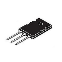
IXXK100N60C3H1 IXYS, IXXK100N60C3H1 Datasheet - Page 5

IXXK100N60C3H1
Manufacturer Part Number
IXXK100N60C3H1
Description
IGBT 600V 170A 695W TO264
Manufacturer
IXYS
Series
XPT™, GenX3™r
Datasheet
1.IXXK100N60C3H1.pdf
(7 pages)
Specifications of IXXK100N60C3H1
Igbt Type
PT
Voltage - Collector Emitter Breakdown (max)
600V
Vce(on) (max) @ Vge, Ic
2.2V @ 15V, 70A
Current - Collector (ic) (max)
170A
Power - Max
695W
Input Type
Standard
Mounting Type
Through Hole
Package / Case
TO-264-3, TO-264AA Variation
Collector- Emitter Voltage Vceo Max
600 V
Collector-emitter Saturation Voltage
2.2 V
Maximum Gate Emitter Voltage
20 V
Continuous Collector Current At 25 C
170 A
Gate-emitter Leakage Current
100 nA
Power Dissipation
695 W
Maximum Operating Temperature
+ 150 C
Minimum Operating Temperature
- 55 C
Mounting Style
Through Hole
Vces, (v)
600
Ic25, Tc = 25°c, Igbt, (a)
170
Ic90, Tc = 90°c, Igbt, (a)
100
Ic110, Tc = 110°c, Igbt, (a)
-
Vce(sat), Typ, Tj = 25°c, Igbt (v)
2.2
Tfi, Typ, Tj = 25°c, Igbt, (ns)
75
Eoff, Typ, Tj = 125°c, Igbt (mj)
-
Eoff, Typ, Tj = 150°c, Igbt (mj)
1.4
Rthjc, Max, Igbt (c/w)
0.18
If, Tc = 90°c, Diode (a)
-
If, Tc = 110°c, Diode (a)
65
Rthjc, Max, Diode (k/w)
0.30
Package Style
TO-264
Lead Free Status / RoHS Status
Lead free / RoHS Compliant
Available stocks
Company
Part Number
Manufacturer
Quantity
Price
Company:
Part Number:
IXXK100N60C3H1
Manufacturer:
ST
Quantity:
230
© 2011 IXYS CORPORATION, All Rights Reserved
3.0
2.5
2.0
1.5
1.0
0.5
200
175
150
125
100
2.5
2.0
1.5
1.0
0.5
75
50
2
25
20
E
T
V
Fig. 17. Inductive Turn-off Switching Times vs.
3
E
R
V
J
off
CE
Fig. 13. Inductive Switching Energy Loss vs.
Fig. 15. Inductive Switching Energy Loss vs.
off
CE
G
= 150ºC , V
= 2
30
= 360V
= 360V
4
Ω ,
50
V
5
GE
40
GE
E
= 15V
E
on
= 15V
on
Junction Temperature
T
6
J
- - - -
- - - -
T
- Degrees Centigrade
Collector Current
Gate Resistance
J
50
= 25ºC
7
I
R
75
C
G
T
- Amperes
J
- Ohms
= 150ºC
8
60
9
R
V
t
f i
G
CE
100
70
= 2
10
= 360V
I
Ω
C
I
, V
= 100A
C
11
= 50A
80
GE
I
I
C
C
= 15V
= 100A
= 50A
12
t
d(off)
125
90
13
- - - -
14
100
180
160
140
120
100
80
60
150
15
7
6
5
4
3
2
5
4
3
2
1
160
150
140
130
120
110
100
2.5
1.5
0.5
180
160
140
120
100
90
80
70
60
80
2
1
0
20
25
2
Fig. 16. Inductive Turn-off Switching Times vs.
Fig. 18. Inductive Turn-off Switching Times vs.
R
V
t
E
R
V
t
T
V
f i
G
CE
3
off
CE
G
Fig. 14. Inductive Switching Energy Loss vs.
f i
J
CE
= 2
= 150ºC, V
= 2
30
= 360V
= 360V
= 360V
Ω
Ω ,
4
I
C
, V
50
= 100A
V
GE
5
GE
I
40
C
GE
t
= 15V
d(on)
= 15V
= 50A
t
E
d(off)
= 15V
Junction Temperature
I
on
6
C
T
- - - -
J
= 50A
- - - -
I
Collector Current
Gate Resistance
- Degrees Centigrade
- - - -
C
50
7
75
I
= 100A
C
- Amperes
R
G
8
- Ohms
60
9
T
IXXK100N60C3H1
IXXX100N60C3H1
J
100
= 150ºC
10
70
T
11
J
= 25ºC
12
80
125
13
90
14
150
15
100
160
140
120
100
80
60
280
260
240
220
200
180
160
140
120
100
80
5
4
3
2
1
0


