734185-1 Tyco Electronics, 734185-1 Datasheet - Page 2
734185-1
Manufacturer Part Number
734185-1
Description
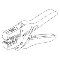
Crimping, Stripping, Cutting Tools & Drills STRIP TOOL
Manufacturer
Tyco Electronics
Type
Wire Stripperr
Datasheet
1.734185-1.pdf
(3 pages)
Specifications of 734185-1
Product
Crimping, Stripping & Cutting Tools & Drills
Wire Gauge Range
28-10
For Use With
PVC, THHN, THHW Wires
Lead Free Status / RoHS Status
na


4. MAINTENANCE AND INSPECTION
Wire Stripper 734185-1 requires no special
maintenance. After use, remove stripped wire and
check to ensure insulation slug has been ejected from
the jaws. Store tool in a clean, dry area.
If the stripping jaws are damaged, replace with Wire
Stripper Blade Assembly 1424946-1. See Figure 3.
For ordering information, refer to Section 6,
ORDERING INFORMATION / REPLACEMENT
PARTS.
Rev A
4. To strip wire, insert wire into front of tool until it
makes contact with the wire stop.
5. Squeeze handle firmly while holding wire
stationary.
6. Re-adjust the insulation thickness adjustment
regulator and wire stop if necessary.
Wire
Strip
Blades
Figure 2
Figure 3
Strip
Length
Wire Stop
(Adjustable)
Wire Stop
Pivot
Spring
5. REMOVAL / INSTALLATION OF REPLACEMENT JAWS
5.1. Jaw Removal
5.2. Jaw Installation
DANGER
1. Open the jaws and position the tool as shown in
Figure 4.
2. Remove the wire stop by squeezing the top tabs
together and lifting the stop from the jaws.
3. Remove the upper stripping jaw by positioning a
screwdriver (on the label side of the tool) between
the tool housing and the jaw.
4. Rotate the screwdriver clockwise and disengage
the upper stripping jaw from the pivot.
5. Remove the upper stripping jaw and the spring.
6. Remove the lower stripping jaw by positioning a
screwdriver near the rear of the lower jaw. Using a
clockwise twisting motion, loosen and remove the
jaw from the pivot pin.
1. Install the lower stripping jaw, with the pivot pin.
2. Position the spring into the throat of the lower
stripping jaw.
3. Position the upper stripping jaw, about 90_ to the
upper tool housing, with the pivot hole end towards
you.
STOP
Wire
Stop
WEAR SAFETY EYE PROTECTION when
installing the compressed spring as instructed in
Steps 4 through 6.
Pivot
(Figure 4 and Figure 5)
(Figure 6)
Figure 4
Upper
Stripping
Jaw
408-8907
2 of 3