ULE-5/12-D24P-C Murata Power Solutions Inc, ULE-5/12-D24P-C Datasheet - Page 14
ULE-5/12-D24P-C
Manufacturer Part Number
ULE-5/12-D24P-C
Description
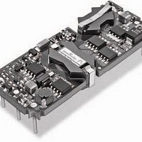
DC/DC Converters & Regulators 60W 24V to 5V 12A POSITVE POLARITY
Manufacturer
Murata Power Solutions Inc
Series
ULEr
Type
Step Downr
Specifications of ULE-5/12-D24P-C
Output Power
60 W
Input Voltage Range
18 V to 36 V
Input Voltage (nominal)
24 V
Number Of Outputs
1
Output Voltage (channel 1)
5 V
Output Current (channel 1)
12 A
Isolation Voltage
2.25 KV
Package / Case Size
Eighth Brick
Product
Isolated
Output Current
12A
Input Voltage
24V
Output Voltage
5V
Screening Level
Industrial
Product Length (mm)
58.4mm
Product Depth (mm)
22.9mm
Mounting Style
Through Hole
Pin Count
8
Package / Case
1/8-Brick
Lead Free Status / RoHS Status
Lead free / RoHS Compliant
Other names
ULE-5/12-D24P-C


is open (or pulled high), and on when the On/Off Control is pulled low with
respect to –V
relay or an open-collector/open-drain drive circuit (optically isolated if appropri-
ate). The drive circuit should be able to sink appropriate current (see Performance
Specs) when activated and withstand appropriate voltage when deactivated.
Applying an external voltage to the On/Off Control when no input power is
applied to the converter can cause permanent damage to the converter.
Trimming Output Voltage
ULE converters have a trim capability that allows users to adjust the output
voltages as listed in the specifi cations. Adjustments to the output voltages can
be accomplished via a trim pot (Figure 6) or a single fi xed resistor as shown
in Figures 7 and 8. A single fi xed resistor can increase or decrease the output
voltage depending on its connection. The resistor should be located close to
the converter and have a TCR less than 100ppm/°C to minimize sensitivity
to changes in temperature. If the trim function is not used, leave the trim pin
fl oating.
Optional Negative-polarity devices (“N” suffi x) are off when the On/Off Control
Dynamic control of the remote on/off function is facilitated with a mechanical
Figure 5. Driving the Negative Polarity On/Off Control Pin
IN
Figure 4. Driving the Positive Polarity On/Off Control Pin
as shown in Figure 5.
ON/OFF CONTROL
-INPUT
CONTROL
+ Vcc
www.murata-ps.com
applicable, will increase the output voltage in this confi guration. A resistor con-
nected from the Trim to the –Output, or –Sense where applicable, will decrease
the output voltage in this confi guration.
affect on the converter's performance and are not recommended. Excessive
voltage differences between V
ment of the output voltage, can cause the overvoltage protection circuitry to
activate (see Performance Specifi cations for overvoltage limits). Power derating
is based on maximum output current and voltage at the converter’s output
pins. Use of trim and sense functions can cause output voltages to increase,
thereby increasing output power beyond the converter's specifi ed rating or
cause output voltages to climb into the output overvoltage region. Therefore:
Figure 7. Trim Connections To Increase Output Voltages Using a Fixed Resistor
A single resistor connected from the Trim to the +Output, or +Sense where
Trim adjustments greater than the specifi ed range can have an adverse
Figure 8. Trim Connections To Decrease Output Voltages
–INPUT
ON/OFF
CONTROL
+INPUT
–INPUT
ON/OFF
CONTROL
+INPUT
–INPUT
ON/OFF
CONTROL
+INPUT
Figure 6. Trim Connections Using A Trimpot
(V
OUT
at pins) x (I
Isolated, High Density, Eighth-Brick
OUT
11 May 2011
1.25–20 Amp, DC/DC Converters
+OUTPUT
–OUTPUT
+OUTPUT
–OUTPUT
+OUTPUT
+SENSE
–OUTPUT
–SENSE
+SENSE
–SENSE
and Sense, in conjunction with trim adjust-
+SENSE
–SENSE
TRIM
TRIM
OUT
TRIM
) <= rated output power
MDC_ULE Series.E01 Page 14 of 26
R1
R2
email: sales@murata-ps.com
TURNS
20kΩ
5-20
ULE Series
LOAD
LOAD
LOAD
Related parts for ULE-5/12-D24P-C
Image
Part Number
Description
Manufacturer
Datasheet
Request
R

Part Number:
Description:
DC/DC TH 12A 24-5V E-Brick
Manufacturer:
Murata Power Solutions Inc
Datasheet:
Part Number:
Description:
DC/DC SM 12A 24-5V E-Brick
Manufacturer:
Murata Power Solutions Inc
Part Number:
Description:
DC/DC TH 12A 48-5V E-Brick
Manufacturer:
Murata Power Solutions Inc
Part Number:
Description:
DC/DC SM 12A 48-5V E-Brick
Manufacturer:
Murata Power Solutions Inc
Part Number:
Description:
DC/DC TH 12A 48-5V E-Brick
Manufacturer:
Murata Power Solutions Inc
Part Number:
Description:
DC/DC SM 12A 48-5V E-Brick
Manufacturer:
Murata Power Solutions Inc

Part Number:
Description:
DC/DC SM 12A 24-5V E-Brick
Manufacturer:
Murata Power Solutions Inc
Part Number:
Description:
DC/DC Converters & Regulators 50W 12V to 5V 10A POSITVE POLARITY
Manufacturer:
Murata Power Solutions Inc
Datasheet:
Part Number:
Description:
DC/DC SM 10A 12-5V E-Brick
Manufacturer:
Murata Power Solutions Inc
Part Number:
Description:
DC/DC TH 10A 12-5V E-Brick
Manufacturer:
Murata Power Solutions Inc
Part Number:
Description:
DC/DC TH 20A 24-2.5V E-Brick
Manufacturer:
Murata Power Solutions Inc
Datasheet:

Part Number:
Description:
Transformers 5Vin 5Vout 200mA 4000Vdc 1:1.33 turn
Manufacturer:
Murata Power Solutions Inc
Datasheet:
Part Number:
Description:
POWER SUPPLY
Manufacturer:
Murata Power Solutions Inc
Datasheet:

Part Number:
Description:
DPM LED MINI 2VDC 3.5DIG LP RED
Manufacturer:
Murata Power Solutions Inc
Datasheet:

Part Number:
Description:
CONV DC/DC 1W 5VIN 5VOUT SIP SGL
Manufacturer:
Murata Power Solutions Inc
Datasheet: