ULE-5/12-D24P-C Murata Power Solutions Inc, ULE-5/12-D24P-C Datasheet - Page 5
ULE-5/12-D24P-C
Manufacturer Part Number
ULE-5/12-D24P-C
Description
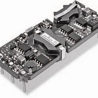
DC/DC Converters & Regulators 60W 24V to 5V 12A POSITVE POLARITY
Manufacturer
Murata Power Solutions Inc
Series
ULEr
Type
Step Downr
Specifications of ULE-5/12-D24P-C
Output Power
60 W
Input Voltage Range
18 V to 36 V
Input Voltage (nominal)
24 V
Number Of Outputs
1
Output Voltage (channel 1)
5 V
Output Current (channel 1)
12 A
Isolation Voltage
2.25 KV
Package / Case Size
Eighth Brick
Product
Isolated
Output Current
12A
Input Voltage
24V
Output Voltage
5V
Screening Level
Industrial
Product Length (mm)
58.4mm
Product Depth (mm)
22.9mm
Mounting Style
Through Hole
Pin Count
8
Package / Case
1/8-Brick
Lead Free Status / RoHS Status
Lead free / RoHS Compliant
Other names
ULE-5/12-D24P-C


Through-hole Pin Changes for 2008
In 2008, for through-hole models only, Murata Power Solutions will gradually
phase over to a different extruded 0.040” (1.02 mm) diameter pin design and
elimination of the spacer standoffs on most models. This will have no effect on
installation, interchangeability, electrical or mechanical specifi cations. Any
machined 0.062” (1.57 mm) diameter pin will transition to a straight wire 0.062”
pin. The new 0.040” pins will insert properly to existing host PC boards and
include an integral pin shoulder to form the mounting plane (Figure 1). There is
no model number change, only a slightly changed appearance. Use the drawings
and table below to identify the new pin design. And, surface mount ULEs are not
affected.
model number suffi x. Older non-RoHS models are also being changed over to
the new extruded pins; however non-RoHS models are not listed in this table.
tion and replaces the plastic standoff spacer. The shoulder diameter is 0.072
+/−0.002" and forms the mounting plane of the converter. The user should
provide suffi cient clearance for a 0.040" pin hole but well below the 0.072"
shoulder diameter. This mounting plane avoids mechanical stress placed on
the converter components. Do not place the components below the converter.
ULE Connections
The ULE series consists of several different PC board layouts sharing a
common outline specifi cation and overall size. This simplifi es interchange-
ability in case the user needs different input or output specifi cations.
include Remote On/Off control pins. Please refer to the following table:
MECHANICAL SPECIFICATIONS
All new production models are RoHS-6 compliant and always use the –C
The “integral” pin shoulder is formed as part of the extruded pin fabrica-
Certain models do not include Sense or Trim connections. All models
Pin depth, see table
Dimensions are in inches (mm)
Figure 1. Extruded 0.040-inch Pin
Keep-out area
0.040 (1.02) dia. pin
Pin shoulder, 0.072 ±0.002 dia. (1.83 ±0.05)
ULE Converter
Drawing not to scale
Seating plane
User’s host
PC Board
www.murata-ps.com
Model Number
ULE-1.5/20-D24P-C
ULE-1.5/20-D48N-C
ULE-1.8/20-D24P-C
ULE-1.8/20-D48N-C
ULE-2.5/20-D24P-C
ULE-2.5/20-D48N-C
ULE-3.3/20-D12P-C
ULE-3.3/20-D24P-C
ULE-3.3/20-D48N-C
ULE-5/10-D12P-C
ULE-5/12-D24P-C
ULE-5/12-D48N-C
ULE-12/4.2-D24P-C
ULE-12/4.2-D48N-C
ULE-24/3-D48N-C
ULE-48/1.25-D48N-C
The pin material is a copper alloy. The pin fi nish is suitable for both leaded
and lead-free solders.
*The “0.040-inch pin depth” is the distance between the mounting plane of the ULE
converter (at the pin shoulder) and the inserted tip of the pin. Therefore it is the length of
pin which the host receiving PC board must accept. The ULE mounting plane interfaces
to the top mounting surface (seating plane) of the user’s PC board. The ULE mounting
plane is established either by an integral pin shoulder (new) or a plastic standoff (older)
but not both. Users should avoid placing components immediately below the converter.
ULE-1.5/20-D24P-C
ULE-1.5/20-D48-C
ULE-1.8/20-D24-C
ULE-1.8/20-D48-C
ULE-2.5/20-D24-C
ULE-2.5/20-D48-C
ULE-3.3/20-D12-C
ULE-3.3/20-D24-C
ULE-3.3/20-D48N-C
ULE-3.3/20-D48P-C
ULE-5/10-D12-C
ULE-5/12-D24-C
ULE-5/12-D48-C
ULE-12/4.2-D24-C
ULE-12/4.2-D48-C
ULE-24/3-D48N-C
ULE-48/1.25-D48-C
Extruded 0.040-inch Pin Confi gurations
The pin fi nish for all models remains as gold plate over nickel underplate.
RoHS Models (-C)
(Volts)
Vout
1.5
1.5
1.8
1.8
2.5
2.5
3.3
3.3
3.3
12
12
24
48
5
5
5
0.040" Pin depth*
Isolated, High Density, Eighth-Brick
0.25 (6.4)
0.25 (6.4)
0.25 (6.4)
0.25 (6.4)
0.19 (4.8)
0.19 (4.8)
0.19 (4.8)
0.25 (6.4)
0.25 (6.4)
0.19 (4.8)
0.19 (4.8)
0.19 (4.8)
0.25 (6.4)
0.25 (6.4)
0.25 (6.4)
0.25 (6.4)
0.25 (6.4)
1.25–20 Amp, DC/DC Converters
11 May 2011
(Amps,
max.)
1.25
Iout
4.2
4.2
20
20
20
20
20
20
20
20
20
10
12
12
3
Number
of Pins
8
8
8
8
8
8
8
8
8
8
8
8
6
6
5
5
MDC_ULE Series.E01 Page 5 of 26
email: sales@murata-ps.com
Dimensions in inches (mm)
On/Off
ULE Series
pin?
yes
yes
yes
yes
yes
yes
yes
yes
yes
yes
yes
yes
yes
yes
yes
yes
Trim
pin?
yes
yes
yes
yes
yes
yes
yes
yes
yes
yes
yes
yes
yes
yes
no
no
Sense
pins?
yes
yes
yes
yes
yes
yes
yes
yes
yes
yes
yes
yes
no
no
no
no
Related parts for ULE-5/12-D24P-C
Image
Part Number
Description
Manufacturer
Datasheet
Request
R

Part Number:
Description:
DC/DC TH 12A 24-5V E-Brick
Manufacturer:
Murata Power Solutions Inc
Datasheet:
Part Number:
Description:
DC/DC SM 12A 24-5V E-Brick
Manufacturer:
Murata Power Solutions Inc
Part Number:
Description:
DC/DC TH 12A 48-5V E-Brick
Manufacturer:
Murata Power Solutions Inc
Part Number:
Description:
DC/DC SM 12A 48-5V E-Brick
Manufacturer:
Murata Power Solutions Inc
Part Number:
Description:
DC/DC TH 12A 48-5V E-Brick
Manufacturer:
Murata Power Solutions Inc
Part Number:
Description:
DC/DC SM 12A 48-5V E-Brick
Manufacturer:
Murata Power Solutions Inc

Part Number:
Description:
DC/DC SM 12A 24-5V E-Brick
Manufacturer:
Murata Power Solutions Inc
Part Number:
Description:
DC/DC Converters & Regulators 50W 12V to 5V 10A POSITVE POLARITY
Manufacturer:
Murata Power Solutions Inc
Datasheet:
Part Number:
Description:
DC/DC SM 10A 12-5V E-Brick
Manufacturer:
Murata Power Solutions Inc
Part Number:
Description:
DC/DC TH 10A 12-5V E-Brick
Manufacturer:
Murata Power Solutions Inc
Part Number:
Description:
DC/DC TH 20A 24-2.5V E-Brick
Manufacturer:
Murata Power Solutions Inc
Datasheet:

Part Number:
Description:
Transformers 5Vin 5Vout 200mA 4000Vdc 1:1.33 turn
Manufacturer:
Murata Power Solutions Inc
Datasheet:
Part Number:
Description:
POWER SUPPLY
Manufacturer:
Murata Power Solutions Inc
Datasheet:

Part Number:
Description:
DPM LED MINI 2VDC 3.5DIG LP RED
Manufacturer:
Murata Power Solutions Inc
Datasheet:

Part Number:
Description:
CONV DC/DC 1W 5VIN 5VOUT SIP SGL
Manufacturer:
Murata Power Solutions Inc
Datasheet: