ULE-5/12-D24P-C Murata Power Solutions Inc, ULE-5/12-D24P-C Datasheet - Page 12
ULE-5/12-D24P-C
Manufacturer Part Number
ULE-5/12-D24P-C
Description
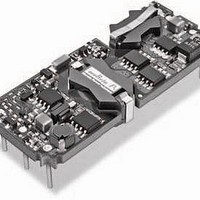
DC/DC Converters & Regulators 60W 24V to 5V 12A POSITVE POLARITY
Manufacturer
Murata Power Solutions Inc
Series
ULEr
Type
Step Downr
Specifications of ULE-5/12-D24P-C
Output Power
60 W
Input Voltage Range
18 V to 36 V
Input Voltage (nominal)
24 V
Number Of Outputs
1
Output Voltage (channel 1)
5 V
Output Current (channel 1)
12 A
Isolation Voltage
2.25 KV
Package / Case Size
Eighth Brick
Product
Isolated
Output Current
12A
Input Voltage
24V
Output Voltage
5V
Screening Level
Industrial
Product Length (mm)
58.4mm
Product Depth (mm)
22.9mm
Mounting Style
Through Hole
Pin Count
8
Package / Case
1/8-Brick
Lead Free Status / RoHS Status
Lead free / RoHS Compliant
Other names
ULE-5/12-D24P-C


Input Fusing
Certain applications and/or safety agencies may require the installation of
fuses at the inputs of power conversion components. Fuses should also be
used if the possibility of sustained, non-current-limited, input-voltage polarity
reversals exist. For Murata Power Solutions ULE 24-60 Watt DC/DC Converters,
you should use fast-blow type fuses, installed in the ungrounded input supply
line, with values no greater than the following.
be observed by the installer. For system safety agency approvals, the convert-
ers must be installed in compliance with the requirements of the end-use
safety standard.
Input Undervoltage Shutdown and Start-Up Threshold
Under normal start-up conditions, devices will not begin to regulate until
the ramping-up input voltage exceeds the Start-Up Threshold Voltage. Once
operating, devices will not turn off until the input voltage drops below the
Undervoltage Shutdown limit. Subsequent re-start will not occur until the input
is brought back up to the Start-Up Threshold. This built in hysteresis prevents
any unstable on/off situations from occurring at a single input voltage.
* The outputs are not intended to sink reverse current.
TECHNICAL NOTES
Input Voltage:
On/Off Control (pin 2)
Input Reverse Polarity Protection
Output Overvoltage Protection
Output Current *
Storage Temperature
Lead Temperature
These are stress ratings. Exposure of devices to greater than any of these conditions
may adversely affect long-term reliability. Proper operation under conditions other than
those listed in the Performance/Functional Specifi cations Table is not implied.
All relevant national and international safety standards and regulations must
Continuous:
Transient (100 mSec. Max.)
12 Volt input models
24 Volt input models
48 Volt input models
12 Volt input models
24 Volt input models
48 Volt input models
Model
12 Volt Input
24 Volt input
48 Volt Input
Absolute Maximum Ratings
Fuse Values
10 Amps
5 Amps
4 Amps
18 Volts
36 Volts
75 Volts
25 Volts
50 Volts
100 Volts
See specifi cations
5 Amps, 10 sec. max.
Magnetic feedback. See note (7).
Current-limited. Devices can with stand
sustained short circuit without damage.
–55 to +125°C.
Refer to solder profi le.
www.murata-ps.com
Start-Up Time
The V
the ramping input voltage crosses the Start-Up Threshold and the fully loaded
output voltage enters and remains within its specifi ed accuracy band. Actual
measured times will vary with input source impedance, external input/output
capacitance, and load. The ULE Series implements a soft start circuit that limits
the duty cycle of its PWM controller at power up, thereby limiting the input
inrush current.
nominal input voltage applied but is turned off via the On/Off Control pin. The
specifi cation defi nes the interval between the point at which the converter is
turned on and the fully loaded output voltage enters and remains within its
specifi ed accuracy band. Similar to the V
to V
external load capacitance.
V
Input Source Impedance
ULE converters must be driven from a low ac-impedance input source. The
DC/DC’s performance and stability can be compromised by the use of highly
inductive source impedances. The input circuit shown in Figure 2 is a practical
solution that can be used to minimize the effects of inductance in the input
traces. For optimum performance, components should be mounted close to
the DC/DC converter. If the application has a high source impedance, low V
models can benefi t of increased external input capacitance.
I/O Filtering, Input Ripple Current, and Output Noise
All models in the ULE 24-60 Watt DC/DC Converters are tested/specifi ed for
input refl ected ripple current and output noise using the specifi ed external input/
output components/circuits and layout as shown in the following two fi gures.
elements, minimizing line voltage variations caused by transient IR drops in
conductors from backplane to the DC/DC. Input caps should be selected for bulk
capacitance (at appropriate frequencies), low ESR, and high rms-ripple-current
ratings. The switching nature of DC/DC converters requires that dc voltage
sources have low ac impedance as highly inductive source impedance can affect
system stability. In Figure 2, C
specifi c system confi guration may necessitate additional considerations.
OUT
The On/Off Control to V
The difference in start up time from V
External input capacitors (C
OUT
is therefore insignifi cant.
IN
V
IN
start-up time is also governed by the internal soft start circuitry and
to V
OSCILLOSCOPE
+
–
OUT
C
C
L
BUS
IN
BUS
TO
Start-Up Time is the interval of time between the point at which
= 33μF, ESR < 700mΩ @ 100kHz
= 12μH
= 220μF, ESR < 100mΩ @ 100kHz
Figure 2. Measuring Input Ripple Current
C
BUS
OUT
L
Isolated, High Density, Eighth-Brick
BUS
BUS
start-up time assumes the converter has its
IN
11 May 2011
in Figure 2) serve primarily as energy-storage
1.25–20 Amp, DC/DC Converters
and L
BUS
CURRENT
IN
IN
simulate a typical dc voltage bus. Your
PROBE
to V
C
to V
IN
OUT
MDC_ULE Series.E01 Page 12 of 26
OUT
email: sales@murata-ps.com
and from On/Off Control to
start-up, the On/Off Control
ULE Series
+INPUT
–INPUT
IN
Related parts for ULE-5/12-D24P-C
Image
Part Number
Description
Manufacturer
Datasheet
Request
R

Part Number:
Description:
DC/DC TH 12A 24-5V E-Brick
Manufacturer:
Murata Power Solutions Inc
Datasheet:
Part Number:
Description:
DC/DC SM 12A 24-5V E-Brick
Manufacturer:
Murata Power Solutions Inc
Part Number:
Description:
DC/DC TH 12A 48-5V E-Brick
Manufacturer:
Murata Power Solutions Inc
Part Number:
Description:
DC/DC SM 12A 48-5V E-Brick
Manufacturer:
Murata Power Solutions Inc
Part Number:
Description:
DC/DC TH 12A 48-5V E-Brick
Manufacturer:
Murata Power Solutions Inc
Part Number:
Description:
DC/DC SM 12A 48-5V E-Brick
Manufacturer:
Murata Power Solutions Inc

Part Number:
Description:
DC/DC SM 12A 24-5V E-Brick
Manufacturer:
Murata Power Solutions Inc
Part Number:
Description:
DC/DC Converters & Regulators 50W 12V to 5V 10A POSITVE POLARITY
Manufacturer:
Murata Power Solutions Inc
Datasheet:
Part Number:
Description:
DC/DC SM 10A 12-5V E-Brick
Manufacturer:
Murata Power Solutions Inc
Part Number:
Description:
DC/DC TH 10A 12-5V E-Brick
Manufacturer:
Murata Power Solutions Inc
Part Number:
Description:
DC/DC TH 20A 24-2.5V E-Brick
Manufacturer:
Murata Power Solutions Inc
Datasheet:

Part Number:
Description:
Transformers 5Vin 5Vout 200mA 4000Vdc 1:1.33 turn
Manufacturer:
Murata Power Solutions Inc
Datasheet:
Part Number:
Description:
POWER SUPPLY
Manufacturer:
Murata Power Solutions Inc
Datasheet:

Part Number:
Description:
DPM LED MINI 2VDC 3.5DIG LP RED
Manufacturer:
Murata Power Solutions Inc
Datasheet:

Part Number:
Description:
CONV DC/DC 1W 5VIN 5VOUT SIP SGL
Manufacturer:
Murata Power Solutions Inc
Datasheet: