L300 Protek, L300 Datasheet
L300
Specifications of L300
Available stocks


Related parts for L300

L300 Summary of contents
Page 1
... Set up Communication Address (0~254)...….20 2.3.7.6 Setting a Pass word…… ............................…20 2.3.7.7 Set up SAVE OPTION...............................…21 2.3.7.8 EXIT Function..........................................…..21 Electronic Load Software Chapter 3 Software Installation...............................22 3.1 Installation................................................…..........22 3.2 Starting the program......….....................................24 3.3 Uninstalling the program.......................................26 L300 user manual CONTENTS ...
Page 2
CAUTION of this instrument must be connected to the protective conductor of the AC line power cord. The AC line plug shall be inserted only in a socket outlet provided with a negated by the use of an extension cord ...
Page 3
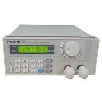
... Chapter 1 General Introduction 1.1 General Introduction The L300 Series Programmable DC Electronic Load is small-sized DC programmable electronic load. with nice appearance. Also it is equipped with backlight LCD display, Numeric keypad and rotary code switch, which let it much easier to use. Voltage, current and power can all be displayed on the LCD or computer and tableau is distinct and clear ...
Page 4
Features 1. LCD display with backlight. 2. Numeric keypad. 3. 1mV resolution 4. Over current protection 5. Over power protection 6. Adjustable constant resistance, constant current and constant power output. 7. All values are set by a numeric keypad ...
Page 5
... Front panel consists of the LCD display, numeric keypad and the rotary dial for entering current, power or resistance values. Please see the diagrams below. Fig2. Front view of L300 DC electronic load 1. LCD display Fig3. EL 300 electronic load LCD Display The upper half of the LCD display: ...
Page 6
... Fig4. L300 Electronic load Keyboard layout 0~9: The Numeric keys Out ON/OFF: Switches the output ON or OFF Store: Saves the present operating values in memory R-set: Sets a constant resistance value START: Starts a previously entered program I-set: Sets the constant current value STOP: Stops a previously entered program P-set Sets a constant power value Recall: Recalls a previously stored set of operating values ...
Page 7
Rear view The fuse can be changed easily using a small screwdriver. Please use a fuse within the range of 0.3-0.5A./250V Fig6. Back view 7 ...
Page 8
General operation 1. Connect the electronic load to the PC Fig 2.1 Connecting the electronic load to the PC 2.2 Function descriptions 2.2.1. Main functions 1. Set a constant current output 2. Set a constant power output 4. Set ...
Page 9
... I-set (setting a constant current value ) Setting a constant DC current output is the first main function of the L300 programmable DC electronic load, The two methods to set a constant DC current input value is using the Numeric keyboard or the rotary button. Please see the following chart for the operation procedure ...
Page 10
Example: To set the current to 3.12A: move the cursor to the left most digit by pressing the ◄ button. Rotate the Rotary dial until the digit Then press the ► button the select the next digit ...
Page 11
... If you have and application that requires Current, Resistance power values that are used continuously or are not changed. It may be desirable to use the Store Data Function. This function stores Current, power and resistance settings in memory for later use. Ten sets of values may be stored in the L300 memory with a location number assigned Procedure. Step 1 Press “ ...
Page 12
... The 10 settings which where saved in memory (2.3.4) can now be retrieved from memory by pressing the Recall button and the numeric keypad number associated with the memory location. This eliminates the need to set up the L300 every time it is used... The recall operation is as follows. ...
Page 13
... The Menu Display The L300 electronic load provides a Menu operation for special functions. The descriptions of these functions are as follows: Displaying the menu: Procedure The operation Methods Step 1 Press “ Menu ” button Step 2 The LCD displays the menu items as a list To scroll through the menu press the,. An arrow (→ ...
Page 14
The MAX Power value maybe set using the Numeric keyboard or rotating the ROTARY button and then pressing the “ OK ” button to confirm. 2.3.7.3 Program Set When PROGRAM SET is selected from the menu, the LCD will display: ...
Page 15
A time duration value from 1 to 7200 seconds (Max) must now be entered for the first current value. This example the time is 2 seconds and is entered as 2, press OK and the LCD will now display ...
Page 16
Pressing the start Key (keypad 7) the following program will run To stop the program, Press the Stop key. (. keypad) 13 this program may be stored in memory by pressing the Store key, then enter a location between ...
Page 17
The second power to be entered is 100W, Enter 100 from the numeric keypad or rotary dial. Press OK, The LCD will now display 7) The time duration for the second power is 60 seconds, enter 60, then press ...
Page 18
Resistance output 1) From the Programs menu select RESISTANCE OUT, press OK 2) The LCD will display 3) Enter the number of resistance values, in this example 3 resistance steps will be used. ...
Page 19
The time duration for the second resistance is 60 seconds, enter 60, then press OK the LCD will now display 8) The third resistance value is 300Ω, enter 300, and then press OK to confirm, and then LCD will ...
Page 20
Users can select a Baud rate by with the UP and DOWN keys or rotating the ROTARY dial , and pressing “ OK ” button on the selected Baud rate. 2.3.7.5 Setting a communication address (0~254) The communication address is ...
Page 21
Set up SAVE OPTION When you select the SAVE OPTION function, the LCD will display as: This function is convenient if you use the same settings day to day. It saves the last Power, Current or Resistance setting before ...
Page 22
Chapter 3 software Installation 3. 1 Software Installation 3.1.1 Insert the monitoring CD into the CDROM drive. The CD Drive will start automatically and the initial window will be displayed as shown in Fig. 3-1 3.1.2 The “Welcome” Screen will ...
Page 23
Fig. 3-3 The License agreement window 3.1.4 Fig. 3-4 displays the user directory the software will be installed in. The default directory path that the program will be installed in is C:\Program Files\Array\PowerMS” If the program installed ...
Page 24
Fig. 3-6 displays a list of existing program folders and the default program folder named “ARRAY/ELECTONIC” where the program will be installed. Fig. 3-6 The Program Folder window 3.1.7 Generally, click “NEXT” and accept the default program folder. Please ...
Page 25
The start screen is display: 3.2.3 Enter the Main Interface screen Fig.3-10 Main Interface of Electronic Load These two lights may the same time. And it is possible that one of them neither ...
Page 26
Uninstall the System It will select “ Uninstall Elect ” from the system start menu. Remember to close the system before uninstalling; otherwise it will be no way to run the command. “ Pause ” : ...