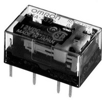
G5CA-1A4-DC24 Omron, G5CA-1A4-DC24 Datasheet - Page 3

G5CA-1A4-DC24
Manufacturer Part Number
G5CA-1A4-DC24
Description
General Purpose / Industrial Relays Sealed SPST-NO 24VDC
Manufacturer
Omron
Series
G5CAr
Specifications of G5CA-1A4-DC24
Coil Resistance
2880 Ohms
Contact Form
SPST - NO
Coil Voltage
24 VDC
Contact Rating
10 A at 250 VAC
Contact Termination
PCB
Mounting Style
PCB
Power Consumption
200 mW
Contact Material
Silver Alloy
Coil Current
10 A
Coil Type
Non-Latching
Relay Type
General Purpose
Coil Voltage Vdc Nom
24V
Contact Current Max
10A
Contact Voltage Ac Nom
250V
Contact Voltage Dc Nom
30V
Contact Configuration
SPST-NO
Current, Rating
10 A
Function
Power
Mounting Type
PCB
Number Of Pins
4
Power, Rating
2500⁄300 VA⁄W
Standards
UL, CSA, RoHS
Termination
Through Hole
Voltage, Control
24 VDC
Voltage, Rating
380 VAC
Subminiature Dimensions
16 × 22 × 11 mm (L × W × H)
Lead Free Status / RoHS Status
Lead free / RoHS Compliant
Lead Free Status / RoHS Status
Lead free / RoHS Compliant, Lead free / RoHS Compliant
Available stocks
Company
Part Number
Manufacturer
Quantity
Price
G5CA
Engineering Data
Dimensions
Note
G5CA-1A(-E)
G5CA-1A4(-H)
Maximum Switching Power
Operating Temperature vs.
Must-operate/Must-release Voltage
Note: The "maximum voltage" is the maximum
100
80
60
40
20
0.7
0.5
0.3
0.1
50
30
15
10
0
−40
7
5
3
1
1
Sample: G5CA-1A DC
No. of samples: 5
AC resistive load
G5CA-1A-E
voltage that can be applied to the relay coil.
DC inductive load
G5CA-1A
G5CA-1A-E
(L/R=7 ms)
DC resistive load
G5CA-1A
G5CA-1A-E
All units are in millimeters unless otherwise indicated.
−20
3
5 7 10
0
AC resistive load
G5CA-1A
AC inductive
load
G5CA-1A
(cos φ=0.4)
11 max.
(10.9)*
30 50 100
3.5
20
1.6
Must-operate voltage
Must-release voltage
Ambient temperature (˚C)
Switching voltage (V)
40
10.16
AC inductive
load
G5CA-1A-E
(cos φ=0.4)
22 max.
300 500 1,000
(21.9)*
60
min.
min.
max.
max.
7.62
X
X
80
Endurance
0.6
500
300
100
70
50
30
10
7
5
3
1
0
0.3
Malfunction Shock
1,000 min.
1,000 min.
2
* Average value
X
Z'
30-VDC resistive load
16 max.
(15.9)*
4
12.7
6
1,000 min.
250-VAC resistive load
8
200
400
600
800
0.4
Y
Y'
110-VAC resistive load
1,000 min.
800
600
400
200
10
Mounting Holes (PCB)
(BOTTOM VIEW)
Tolerance: ±0.1 mm
Switching current (A)
elliptic holes
2.54
Two, 1 dia.
12
Y
Y'
Shock direction
Unit: m/s
X
14
1,000 min.
1,000 min.
2.54
16
Z
10.16
X'
X'
2
17.78
Z
Z'
Ambient Temperature vs.
Maximum Coil Voltage
200
180
160
150
140
130
120
100
80
60
2
0
No. of samples: 10
Measured value: The value at which
Standard:
Two, 1 dia. hole
20
12.7
30
Continuous max.
permissile voltage (15 A)
Note: Orientation marks are
Terminal Arrangement/
Internal Connections
40
(BOTTOM VIEW)
indicated as follows:
Continuous max.
permissile voltage (10 A)
50
malfunction occurs
in the contact when
the contact is
subjected to shock
three times each in
six directions for
three axes.
200 m/s
(No coil polarity)
1
Ambbient temperature (˚C)
4
60
2
3
70
G5CA
2
80
90
3


