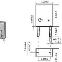
CSBLA455KEC8-B0 Murata, CSBLA455KEC8-B0 Datasheet - Page 15

CSBLA455KEC8-B0
Manufacturer Part Number
CSBLA455KEC8-B0
Description
Resonators 455kHz 0.5%
Manufacturer
Murata
Series
CSBLAr
Datasheets
1.CSBLA400KECE-B0.pdf
(42 pages)
2.CSBLA455KEC8-B0.pdf
(1 pages)
3.CSACS8.00MT-TC.pdf
(21 pages)
Specifications of CSBLA455KEC8-B0
Tolerance
0.5 %
Termination Style
Through Hole
Operating Temperature Range
- 20 C to + 80 C
Dimensions
7 mm W x 9 mm L x 3.5 mm H
Frequency Stability
0.3 %
Frequency
455 KHz
Lead Free Status / RoHS Status
Lead free / RoHS Compliant
Available stocks
Company
Part Number
Manufacturer
Quantity
Price
Company:
Part Number:
CSBLA455KEC8-B0
Manufacturer:
MURATA
Quantity:
1 000
!Note
Generally, basic oscillation circuits can be grouped into
the following 3 categories.
q Use of positive feedback
w Use of negative resistance element
e Use of delay in transfer time or phase
In the case of ceramic resonators, quarts crystal
oscillators, and LC oscillators, positive feedback is the
circuit of choice.
Among the positive feedback oscillation circuit using an
LC, the tuning type anti-coupling oscillation circuit,
Colpitts and Hartley circuits are typically used.
See Fig. 2-6.
In Fig. 2-6, a transistor, which is the most basic
amplifier, is used.
The oscillation frequencies are approximately the same
as the resonance frequency of the circuit consisting of L,
C
and L
represented by the following formulas. (Refer to Note 3
on page 15.)
In an LC network, the inductor is replaced by a ceramic
resonator, taking advantage of the fact that the
resonator becomes inductive between resonant and anti-
resonant frequencies.
This is most commonly used in the Colpitts circuit.
The operating principle of these oscillation circuits can
be seen in Fig. 2-7. Oscillation occurs when the
following conditions are satisfied.
In Colpitts circuit, an inverter of
it is inverted more than
feedback circuit. The operation with a ceramic resonator
can be considered the same.
(Colpitts Circuit)
fosc. =
(Hartley Circuit)
fosc. =
2. Basic Oscillation Circuits
L1
and C
Loop Gain G =
Phase Amount
Please read rating and !CAUTION (for storage, operating, rating, soldering, mounting and handling) in this PDF catalog to prevent smoking and/or burning, etc.
This catalog has only typical specifications. Therefore, you are requested to approve our product specifications or to transact the approval sheet for product specificaions before ordering.
2
in the Hartley circuit. These frequencies can be
2
2
L2
C (L
in the Colpitts circuit or consisting of L
L · C
1
=
C
1
1
+L
L1
L1
1
+ C
· C
2
)
+
·
L2
L2
U1
2
= 360 n (n = 1, 2, ···)
2
= 180 with L and C in the
1
= 180 is used, and
1
(2-4)
(2-5)
(2-6)
Fig. 2-6 Basic Configuration of LC Oscillation Circuit
Colpitts Circuit
Principles of CERALOCK
C
L1
Fig. 2-7 Principle of Oscillation
L
C
L2
Amplifier
Feedback Circuit
Mu Factor :
Phase Shift :
Feedback Ratio :
Phase Shift :
1
2
Oscillation Conditions
Loop Gain G=
Phase Shift =
Hartley Circuit
L
1
C
P17E14.pdf 04.8.24
·
L
1
2
+
U1
2
=360 n
®
2
13
2


