CSBLA455KEC8-B0 Murata, CSBLA455KEC8-B0 Datasheet - Page 12
CSBLA455KEC8-B0
Manufacturer Part Number
CSBLA455KEC8-B0
Description
Resonators 455kHz 0.5%
Manufacturer
Murata
Series
CSBLAr
Datasheets
1.CSBLA400KECE-B0.pdf
(42 pages)
2.CSBLA455KEC8-B0.pdf
(1 pages)
3.CSACS8.00MT-TC.pdf
(21 pages)
Specifications of CSBLA455KEC8-B0
Tolerance
0.5 %
Termination Style
Through Hole
Operating Temperature Range
- 20 C to + 80 C
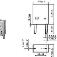
Dimensions
7 mm W x 9 mm L x 3.5 mm H
Frequency Stability
0.3 %
Frequency
455 KHz
Lead Free Status / RoHS Status
Lead free / RoHS Compliant
Available stocks
Company
Part Number
Manufacturer
Quantity
Price
Company:

Part Number:
CSBLA455KEC8-B0
Manufacturer:
MURATA
Quantity:
1 000


2
!Note
Fig. 2-1 shows the symbol for a ceramic resonator. The
impedance and phase characteristics measured between
the terminals are shown in Fig. 2-2. This illustrates that
the resonator becomes inductive in the frequency zone
between the frequency Fr (resonant frequency), which
provides the minimum impedance, and the frequency Fa
(anti-resonant frequency), which provides the maximum
impedance.
It becomes capacitive in other frequency zones. This
means that the mechanical vibration of a two terminal
resonator can be replaced equivalently with a
combination of series and parallel resonant circuits
consisting of an inductor : L, a capacitor : C, and a
resistor : R. In the vicinity of the specific frequency
(Refer to Note 1 on page 12.), the equivalent circuit can
be expressed as shown in Fig. 2-3.
Fr and Fa frequencies are determined by the
piezoelectric ceramic material and the physical
parameters. The equivalent circuit constants can be
determined from the following formulas. (Refer to Note
2 on page 12.)
Considering the limited frequency range of FrVFVFa,
the impedance is given as Z=Re+j Le (LeU0) as shown
in Fig. 2-4, and CERALOCK
inductance Le (H) having the loss Re ( ).
10
Fr=1/2
Fa=1/2
Qm=1/2 FrC
(Qm : Mechanical Q)
1. Equivalent Circuit Constants
2
Please read rating and !CAUTION (for storage, operating, rating, soldering, mounting and handling) in this PDF catalog to prevent smoking and/or burning, etc.
This catalog has only typical specifications. Therefore, you are requested to approve our product specifications or to transact the approval sheet for product specificaions before ordering.
L
L
Principles of CERALOCK
1
1
C
C
1
R
1
1
C
1
0
/(C
1
+C
0
)=Fr 1+C
®
should work as an
1
/C
0
(2-1)
(2-2)
(2-3)
Fig. 2-2 Impedance and Phase Characteristics of CERALOCK
Fig. 2-3 Electrical Equivalent Circuit of CERALOCK
Fig. 2-1 Symbol of the Two Terminal CERALOCK
Fig. 2-4 Equivalent Circuit of CERALOCK
Symbol
10
10
10
10
-90
R
L
C
C
10
90
0
5
4
3
2
1
in the Frequency Band FrVFVFa
1
1
0
: Equivalent Inductance
: Equivalent Resistance
: Equivalent Capacitance
: Parallel Equivalent Capacitance
Re
Impedance between Two Terminals Z=R+jx
(R : Real Component, X : Impedance Component)
Phase
Re : Effective Resistance
Le : Effective Inductance
L
1
Fr
®
=tan
C
C
1
0
-1
X/R
Fa
Le
R
1
Frequency (kHz)
P17E14.pdf 04.8.24
®
®
®
®
Related parts for CSBLA455KEC8-B0
Image
Part Number
Description
Manufacturer
Datasheet
Request
R

Part Number:
Description:
Murata Microblower 20x20 DCDC Driver Board - Samples Only
Manufacturer:
Murata
Part Number:
Description:
357-036-542-201 CARDEDGE 36POS DL .156 BLK LOPRO
Manufacturer:
Murata
Datasheet:
Part Number:
Description:
Manufacturer:
Murata
Datasheet:
Part Number:
Description:
Manufacturer:
Murata
Datasheet:
Part Number:
Description:
Manufacturer:
Murata
Datasheet:
Part Number:
Description:
Manufacturer:
Murata
Datasheet:
Part Number:
Description:
Manufacturer:
Murata
Datasheet:
Part Number:
Description:
Manufacturer:
Murata
Datasheet:
Part Number:
Description:
Manufacturer:
Murata
Datasheet:
Part Number:
Description:
BLM21BD751SN1On-Board Type (DC) EMI Suppression Filters
Manufacturer:
Murata
Datasheet:
Part Number:
Description:
BLM15AG100SN1On-Board Type (DC) EMI Suppression Filters
Manufacturer:
Murata
Datasheet:
Part Number:
Description:
NFE31PT222Z1E9On-Board Type (DC) EMI Suppression Filters
Manufacturer:
Murata
Datasheet:
Part Number:
Description:
Chip Coil
Manufacturer:
Murata
Datasheet:
Part Number:
Description:
Chip Coil
Manufacturer:
Murata
Datasheet: