BNX002-01 Murata, BNX002-01 Datasheet - Page 179
BNX002-01
Manufacturer Part Number
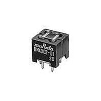
BNX002-01
Description
EMI/RFI Suppressors & Ferrites 50V 10A EMI FILTER
Manufacturer
Murata
Series
BNXr
Specifications of BNX002-01
Lead Spacing
2.5 mm
Shielding
Unshielded
Product
EMI Filters
Impedance
50 Ohms
Maximum Dc Current
10 Amps
Operating Temperature Range
- 30 C to + 85 C
Termination Style
Radial
Length/height, External
13mm
Frequency Max
1GHz
External Width
12mm
Voltage Rating Vdc
50V
External Depth
11mm
Rohs Compliant
Yes
Frequency Range
1MHz To 1GHz
Dc Current Rating
10A
Ferrite Mounting
Through Hole
Lead Free Status / RoHS Status
Lead free / RoHS Compliant
Available stocks
Company
Part Number
Manufacturer
Quantity
Price
Company:

Part Number:
BNX002-01
Manufacturer:
HUAWEI
Quantity:
230
Company:
Part Number:
BNX002-01
Manufacturer:
MURATA
Quantity:
5 946
Part Number:
BNX002-01
Manufacturer:
MURATA/村田
Quantity:
20 000
Company:
Part Number:
BNX002-01P500
Manufacturer:
M-SYSTEM
Quantity:
1
Company:
Part Number:
BNX002-01SM02-30
Manufacturer:
JST
Quantity:
724


DLp Chip Common Mode Choke Coil
!Note
DLP
DLW
DLM
2. Solder Paste Printing and Adhesive Application
When reflow soldering the
coils, the printing must be conducted in accordance with
the following cream solder printing conditions.
If too much solder is applied, the chip will be prone to
damage by mechanical and thermal stress from the PCB
and may crack.
Standard land dimensions should be used for resist and
copper foil patterns.
• Please read rating and !CAUTION (for storage, operating, rating, soldering, mounting and handling) in this catalog to prevent smoking and/or burning, etc.
• This catalog has only typical specifications because there is no space for detailed specifications. Therefore, please review our product specifications or consult the approval sheet for product specifications before ordering.
Series
DLP0NS/11S/11T/31S/DLM11G
oGuideline of solder paste thickness:
*Solderability is subject to reflow conditions and
thermal conductivity. Please make sure that your
product has been evaluated in view of your
specifications with our product being mounted to your
product.
DLP0NS
DLP11S
DLP11T
DLP31S
DLM11G
DLP2AD/31D
100-150 m: DLW21S/21H/31S,
150-200 m: DLP31D/31S, DLM2HG,
DLW5AH/5BS/5BT
Series
c
d
a
chip common mode choke
5.5
2.9
0.9
b
0.3
0.7
0.5
1.0
0.5
a
0.55
0.55
0.3
0.6
0.5
DLP0NS/11S/11T/1ND/2AD/DLM11G
DLW5AH/5BS/5BT
a
b
Solder Paste Printing
0.3
0.3
0.3
0.7
0.4
c
Soldering and Mounting
0.55
0.55
0.5
2.1
0.7
d
DLW21S/H
DLW31S
DLP1ND
DLP2AD
DLP31D
Series
Series
DLW21S/21H/31S
DLM2HG
a
b
0.55
0.3
1.0
a
0.8
1.6
a
0.3
0.4
0.8
b
2.6
3.7
1.0
4.0
b
0.25
0.2
0.4
0.5
0.4
c
c
When flow soldering the
apply the adhesive in accordance with the following
conditions.
If too much adhesive is applied, then it may overflow into
the land or termination areas and yield poor solderability.
In contrast, if insufficient adhesive is applied, or if the
adhesive is not sufficiently hardened, then the chip may
become detached during flow soldering process.
0.4
0.5
0.8
1.2
1.6
d
d
DLP31S/DLM2HG/DLP31D
Apply 0.3mg of bonding agent at each chip.
Coating Position of
Bonding Agent
Coating Position of
Bonding Agent
DLP31D
Adhesive Application
chip common mode choke
DLM2HG
Coating Position of
Bonding Agent
DLP31S
(in mm)
coils,
177
Mar.28,2011
C31E.pdf
Related parts for BNX002-01
Image
Part Number
Description
Manufacturer
Datasheet
Request
R

Part Number:
Description:
Murata Microblower 20x20 DCDC Driver Board - Samples Only
Manufacturer:
Murata
Part Number:
Description:
357-036-542-201 CARDEDGE 36POS DL .156 BLK LOPRO
Manufacturer:
Murata
Datasheet:
Part Number:
Description:
Manufacturer:
Murata
Datasheet:
Part Number:
Description:
Manufacturer:
Murata
Datasheet:
Part Number:
Description:
Manufacturer:
Murata
Datasheet:
Part Number:
Description:
Manufacturer:
Murata
Datasheet:
Part Number:
Description:
Manufacturer:
Murata
Datasheet:
Part Number:
Description:
Manufacturer:
Murata
Datasheet:
Part Number:
Description:
Manufacturer:
Murata
Datasheet:
Part Number:
Description:
BLM21BD751SN1On-Board Type (DC) EMI Suppression Filters
Manufacturer:
Murata
Datasheet:
Part Number:
Description:
BLM15AG100SN1On-Board Type (DC) EMI Suppression Filters
Manufacturer:
Murata
Datasheet:
Part Number:
Description:
NFE31PT222Z1E9On-Board Type (DC) EMI Suppression Filters
Manufacturer:
Murata
Datasheet:
Part Number:
Description:
Chip Coil
Manufacturer:
Murata
Datasheet:
Part Number:
Description:
Chip Coil
Manufacturer:
Murata
Datasheet: