BNX002-01 Murata, BNX002-01 Datasheet - Page 178
BNX002-01
Manufacturer Part Number
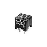
BNX002-01
Description
EMI/RFI Suppressors & Ferrites 50V 10A EMI FILTER
Manufacturer
Murata
Series
BNXr
Specifications of BNX002-01
Lead Spacing
2.5 mm
Shielding
Unshielded
Product
EMI Filters
Impedance
50 Ohms
Maximum Dc Current
10 Amps
Operating Temperature Range
- 30 C to + 85 C
Termination Style
Radial
Length/height, External
13mm
Frequency Max
1GHz
External Width
12mm
Voltage Rating Vdc
50V
External Depth
11mm
Rohs Compliant
Yes
Frequency Range
1MHz To 1GHz
Dc Current Rating
10A
Ferrite Mounting
Through Hole
Lead Free Status / RoHS Status
Lead free / RoHS Compliant
Available stocks
Company
Part Number
Manufacturer
Quantity
Price
Company:

Part Number:
BNX002-01
Manufacturer:
HUAWEI
Quantity:
230
Company:
Part Number:
BNX002-01
Manufacturer:
MURATA
Quantity:
5 946
Part Number:
BNX002-01
Manufacturer:
MURATA/村田
Quantity:
20 000
Company:
Part Number:
BNX002-01P500
Manufacturer:
M-SYSTEM
Quantity:
1
Company:
Part Number:
BNX002-01SM02-30
Manufacturer:
JST
Quantity:
724


DL
o
!Note
176
1. Standard Land Pattern Dimensions
DLM11G
DLM2HG
DLP0NS
DLP11S
DLP11T
DLP1ND
DLP2AD
DLP31S
DLP31D
DLW21S
DLW21H
DLW31SN
DLW5AH
DLW5B
PCB Warping
PCB should be designed so that products are not
subjected to the mechanical stress caused by warping
the board.
• Please read rating and !CAUTION (for storage, operating, rating, soldering, mounting and handling) in this catalog to prevent smoking and/or burning, etc.
• This catalog has only typical specifications because there is no space for detailed specifications. Therefore, please review our product specifications or consult the approval sheet for product specifications before ordering.
p
Chip Common Mode Choke Coil
DLW5AH/5B
DLM2HG
DLP0NS
oReflow and Flow
oReflow Soldering
DLP2AD
0.30
0.90
0.9
2.9
5.5
0.5
0.25
1.75
1.0
4.0
DLP11S
DLM11G
DLP31S
0.55
1.95
1.5
0.5
1.0 0.6 1.0
Soldering and Mounting
Products should be located in the sideways direction
(Length: a<b) to the mechanical stress.
Poor example
Do not use gild pattern; excess soldering heat may dissolve
metal of a copper wire.
1
2
3
DLW21S/21H/31SN
DLW21S/H
DLW31SN
: If the pattern is made with wider than 1.2mm (DLW21) /
: If the pattern is made with less than 0.4mm, in the worst
: If the pattern is made with wider than 0.8mm (DLW21) /
DLP11T
1.6mm (DLW31S) it may result in components turning
around, because melting speed is different. In the worst
case, short circuit between lines may occur.
case, short circuit between lines may occur due to spread
of soldering paste or mount placing accuracy.
1.6mm (DLW31SN), the bending strength will be reduced.
Series
a
b
3
1.55
0.55
DLP31D
0.8
1.6
a
2.6
3.7
Good example
0.8 Pitch
b
DLP1ND
b
Land Pattern
+ Solder Resist
Land Pattern
Solder Resist
a
2.8
0.4
0.4
0.4
0.2
c
1.4
0.4
1.2
1.6
d
(in mm)
Mar.28,2011
C31E.pdf
Related parts for BNX002-01
Image
Part Number
Description
Manufacturer
Datasheet
Request
R

Part Number:
Description:
Murata Microblower 20x20 DCDC Driver Board - Samples Only
Manufacturer:
Murata
Part Number:
Description:
357-036-542-201 CARDEDGE 36POS DL .156 BLK LOPRO
Manufacturer:
Murata
Datasheet:
Part Number:
Description:
Manufacturer:
Murata
Datasheet:
Part Number:
Description:
Manufacturer:
Murata
Datasheet:
Part Number:
Description:
Manufacturer:
Murata
Datasheet:
Part Number:
Description:
Manufacturer:
Murata
Datasheet:
Part Number:
Description:
Manufacturer:
Murata
Datasheet:
Part Number:
Description:
Manufacturer:
Murata
Datasheet:
Part Number:
Description:
Manufacturer:
Murata
Datasheet:
Part Number:
Description:
BLM21BD751SN1On-Board Type (DC) EMI Suppression Filters
Manufacturer:
Murata
Datasheet:
Part Number:
Description:
BLM15AG100SN1On-Board Type (DC) EMI Suppression Filters
Manufacturer:
Murata
Datasheet:
Part Number:
Description:
NFE31PT222Z1E9On-Board Type (DC) EMI Suppression Filters
Manufacturer:
Murata
Datasheet:
Part Number:
Description:
Chip Coil
Manufacturer:
Murata
Datasheet:
Part Number:
Description:
Chip Coil
Manufacturer:
Murata
Datasheet: