FP1189-G TriQuint, FP1189-G Datasheet - Page 9
FP1189-G
Manufacturer Part Number
FP1189-G
Description
RF Mixer 50-4000MHz +27dBm P1dB
Manufacturer
TriQuint
Datasheet
1.FP1189-PCB2140S.pdf
(11 pages)
Specifications of FP1189-G
Frequency Range
915 MHz to 2450 MHz
Maximum Operating Temperature
+ 160 C
Minimum Operating Temperature
- 55 C
Mounting Style
SMD/SMT
Operating Supply Voltage
8 V
Supply Current
125 mA
Package / Case
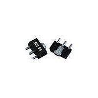
SOT-89
Noise Figure
2.7 dB
Lead Free Status / RoHS Status
Lead free / RoHS Compliant
Other names
1066922
Available stocks
Company
Part Number
Manufacturer
Quantity
Price
Company:

Part Number:
FP1189-G
Manufacturer:
WJ
Quantity:
12 800
Part Number:
FP1189-G
Manufacturer:
WJ
Quantity:
20 000


The 2450 MHz Reference Circuit is shown for design purposes only. An
evaluation board is not readily available for this application. The reader can
obtain an FP1189-PCB2140S evaluation board and modify it with the circuit
shown to achieve the performance shown in this reference design. Only two
component changes are required (C4 and L3) from the FP1189-PCB2140S
evaluation board.
WJ Communications, Inc • Phone 1-800-WJ1-4401 • FAX: 408-577-6621 • e-mail: sales@wj.com • Web site: www.wj.com, www.TriQuint.com
P=
Z=
POR T
1
50 Ohm
Frequency
S21 – Gain
S11 – Input Return Loss
S22 – Output Return Loss
Output P1dB
Output IP3
Drain Voltage
Drain Current
(+12 dBm / tone, 1 MHz spacing)
ID =
CAP
C =
ID =
14 mil GETEK
The main microstrip line has a line impedance of 50 Ω.
CAP
C =
C1
22 pF
FP1189
½-Watt HFET
C4
1.2 pF
C4
Typical RF Performance, 25°C
TM
L os s=
TLINP
Eef f=
ML200DSS (ε
I D =
Z 0=
F 0=
ID =
ID =
L =
RES
R =
IN D
The lengths shown in the microstrip lines are referenced from the component or pin edge-to-edge.
L=
T L2
5 0 Ohm
4 5 mil
4 .2
0
0 M Hz
-Vgg
R1
100 Ohm
L1
18 nH
r
Loss=
= 4.2)
TLINP
Eef f=
MHz
Z0=
F0=
dBm
dBm
ID =
ID =
ID =
mA
CAP
C =
CAP
C =
L=
dB
dB
dB
V
TL1
50 Ohm
13 5 mil
4.2
0
0 MHz
C3
33 pF
C2
DN P pF
The application circuit is matched for output power.
Reference Design: 2450 MHz
+27.5
2450
+38
100
+8
13.2
ID =
-7.6
RES
R =
-36
R2
10 Ohm
+28.1
2450
+40
125
+8
1
NET=
SU BC KT
ID =
Q1
"FP1189"
2
Loss=
TLINP
Eef f=
Z0=
F0=
-10
-15
-20
-25
-30
ID =
15
10
L=
-5
5
0
Ref. Desig.
C1, C7, C9
C3
C4
C5
C8
L1, L2
L3
R1
R2
Q1
C2, C4, C6, C11
TL3
50 Ohm
8 0 mil
4.2
0
0 MHz
2200
DB(|S[1,1]|)
2300
Specifications and information are subject to change without notice.
ID =
IN D
L=
L3
1.8 nH
Value
22 pF
33 pF
1.2 pF
0.5 pF
0.1 μF
18 nH
1.8 nH
100 Ω
10 Ω
FP1189
DB(|S[2,1]|)
Bill of Materials
2400
Frequency (MHz)
S-Parameters
Part style
Chip capacitor
Chip capacitor
Chip capacitor
Chip capacitor
Chip capacitor
Multilayer chip inductor
Multilayer chip resistor
Chip resistor
Chip resistor
WJ 0.5W HFET
Do Not Place
Loss=
TLINP
Eef f=
Z0=
F0=
ID =
L=
TL4
50 Ohm
3 5 mil
4.2
0
0 MHz
DB(|S[2,2]|)
2500
ID =
ID =
ID =
CAP
C =
CAP
C =
CAP
C =
Vds = 8 V @ 125 mA
C8
100000 pF
C6
DN P pF
C7
22 pF
ID =
Page 9 of 11
CAP
C =
C5
0.5 pF
ID =
2600
IN D
L=
L2
18 nH
ID =
CAP
C =
C7
22 pF
Size
0603
0805
0603
0603
1206
0603
0603
0603
0603
SOT-89
January 2008
P=
Z=
POR T
2700
2
50 Ohm
Related parts for FP1189-G
Image
Part Number
Description
Manufacturer
Datasheet
Request
R

Part Number:
Description:
RF Modules & Development Tools 2140MHz Eval Brd 14.5dB Gain
Manufacturer:
TriQuint
Datasheet:
Part Number:
Description:
RF Modules & Development Tools 900MHz Eval Brd 20.5dB Gain
Manufacturer:
TriQuint
Datasheet:
Part Number:
Description:
RF Modules & Development Tools 1900MHz Eval Brd 15.5dB Gain
Manufacturer:
TriQuint
Datasheet:

Part Number:
Description:
Manufacturer:
TriQuint
Datasheet: