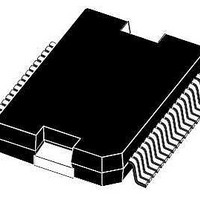
L6230PD STMicroelectronics, L6230PD Datasheet - Page 15

L6230PD
Manufacturer Part Number
L6230PD
Description
Motor / Motion / Ignition Controllers & Drivers DMOS Driver 3-Phase Brushless DC Motor
Manufacturer
STMicroelectronics
Type
DMOS Driverr
Datasheet
1.L6230PD.pdf
(24 pages)
Specifications of L6230PD
Product
Fan / Motor Controllers / Drivers
Operating Supply Voltage
8 V to 52 V
Supply Current
1.4 A
Mounting Style
SMD/SMT
Package / Case
PowerSO-36
Operating Temperature
- 40 C to + 125 C
Lead Free Status / RoHS Status
Lead free / RoHS Compliant
Available stocks
Company
Part Number
Manufacturer
Quantity
Price
Company:
Part Number:
L6230PD
Manufacturer:
STMicroelectronics
Quantity:
310
L6230
6
6.1
Application information
Some typical applications using L6230 are shown in this paragraph. A high quality ceramic
capacitor (C
VS
power supply and reduce high frequency transients generated by the switching. The
capacitor (C
an over current is detected (see overcurrent protection). The current sensing inputs
(SENSE
as possible in the layout. The sense resistors should be non-inductive resistors to minimize
the dI/dt transients across the resistors. To increase noise immunity, unused logic pins are
best connected to 5 V (high logic level) or GND (low logic level) (see pin description). It is
recommended to keep power ground and signal ground separated on PCB.
Table 8.
The examples reported describe some typical application to drive a 3-phase BLDC motor
using L6230 device.
In the first example is shown a field oriented control (FOC) system, with this method it is
possible to provide smooth and precise motor control of BLDC motors.
A six-step driving method with current control is reported in the second example, the inputs
sequence is generated by external controller and the L6230 comparator is used to obtain
the information for the peak current control.
Finally, the third example shows how to implement a sensorless motor control system, the
information on rotor position is achieved by BEMF zero-crossing detection.
Field oriented control driving method
In this configuration (see
channel. The sensing signals coming from the output power stage are conditioned by
external operational amplifiers which provide the proper feedback signals to the AtoD
converter and the system controller. According to the feedback signals the six input lines are
generated by the controller.
Note that some filtering and level shifting RC networks should be added between the sense
resistor and the correspondent op-amp input.
A
and VS
X
) should be connected to the sensing resistors R
EN
2
B
Component values for typical application
) in the range of 100 nF to 200 nF should be placed between the power pins
and ground near the L6230 to improve the high frequency filtering on the
) connected from the DIAG-EN input to ground sets the shut down time when
Component
C
C
R
BOOT
C
C
C
D
D
EN
EN
1
2
P
1
2
Figure
Doc ID 18094 Rev 1
14) three sensing resistors are required, one for each
SENSE
with a trace length as short
1N4148
1N4148
100 µF
100 nF
220 nF
100 kΩ
5.6 nF
Value
10 nF
Application information
15/24


