FB180SA10P Vishay, FB180SA10P Datasheet
FB180SA10P
Specifications of FB180SA10P
Available stocks


Related parts for FB180SA10P


FB180SA10P Summary of contents
Page 1
... SYMBOL TEST CONDITIONS ° 100 ° ° ( ( ( (3) dV/ Stg V ISO M4 screw = 180 A (see fig. 12) AS 150 ° DiodesEurope@vishay.com FB180SA10P Vishay Semiconductors MAX. UNITS 180 120 A 720 480 W 2.7 W/°C ± 700 mJ 180 5.7 V/ 150 °C 2.5 kV 1.3 Nm www.vishay.com 1 ...
Page 2
... FB180SA10P Vishay Semiconductors THERMAL RESISTANCE PARAMETER Junction to case Case to sink, flat, greased surface ELECTRICAL CHARACTERISTICS (T PARAMETER Drain to source breakdown voltage Breakdown voltage temperature coefficient Static drain to source on-resistance Gate threshold voltage Forward transconductance Drain to source leakage current Gate to source forward leakage ...
Page 3
... Document Number: 94541 For technical questions within your region, please contact one of the following: Revision: 30-Jul-10 DiodesAmericas@vishay.com, DiodesAsia@vishay.com, Power MOSFET, 180 A ° 100 Fig Normalized On-Resistance vs. Temperature 20000 15000 10000 ° 100 9 10 FB180SA10P Vishay Semiconductors 2 180A D 2.0 1.5 1.0 0 10V GS 0.0 ...
Page 4
... FB180SA10P Vishay Semiconductors 1000 T = 150 C ° J 100 10 ° 0.1 0.2 0.6 1.0 V ,Source-to-Drain Voltage (V) SD Fig Typical Source Drain Diode Forward Voltage 10000 OPERATION IN THIS AREA LIMITED BY R DS(on) 1000 10us 100us 100 1ms 10ms ° 150 C ° J Single Pulse 100 ...
Page 5
... For technical questions within your region, please contact one of the following: Revision: 30-Jul-10 DiodesAmericas@vishay.com, DiodesAsia@vishay.com, Power MOSFET, 180 A SINGLE PULSE (THERMAL RESPONSE) 0.0001 0.001 t , Rectangular Pulse Duration (sec) 1 1500 1200 15 V Driver + Fig. 12c - Maximum Avalanche Energy vs. Drain Current ( FB180SA10P Vishay Semiconductors Notes: 1. Duty factor Peak thJC C 0.01 0.1 ...
Page 6
... FB180SA10P Vishay Semiconductors Reverse Recovery Current Re-Applied Voltage www.vishay.com For technical questions within your region, please contact one of the following: 6 DiodesAmericas@vishay.com, DiodesAsia@vishay.com, Power MOSFET, 180 A Current regulator Same type as D.U.T. 50 kΩ 0.2 µF 0.3 µF D.U. Current sampling resistors Fig. 13b - Gate Charge Test Circuit ...
Page 7
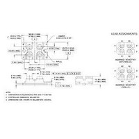
... DiodesAmericas@vishay.com, DiodesAsia@vishay.com, Power MOSFET, 180 180 Power MOSFET - Generation 5 MOSFET silicon DBC construction - Current rating (180 = 180 A) - Single switch - SOT-227 - Voltage rating (10 = 100 Lead (Pb)-free CIRCUIT S G (2) LINKS TO RELATED DOCUMENTS FB180SA10P Vishay Semiconductors CIRCUIT DRAWING Lead assignment D ( (1-4) www.vishay.com/doc?95036 www.vishay.com/doc?95037 www.vishay.com DiodesEurope@vishay.com ...
Page 8
... Vishay product could result in personal injury or death. Customers using or selling Vishay products not expressly indicated for use in such applications their own risk and agree to fully indemnify and hold Vishay and its distributors harmless from and against any and all claims, liabilities, expenses and damages arising or resulting in connection with such use or sale, including attorneys fees, even if such claim alleges that Vishay or its distributor was negligent regarding the design or manufacture of the part ...