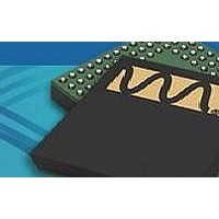
WM9090ECS/R Wolfson Microelectronics, WM9090ECS/R Datasheet - Page 41

WM9090ECS/R
Manufacturer Part Number
WM9090ECS/R
Description
Audio CODECs Audio Subsystem w/ capless headphones
Manufacturer
Wolfson Microelectronics
Specifications of WM9090ECS/R
Interface Type
2-Wire, l2C
Thd Plus Noise
80 dB
Ic Function
Ultra Low Power Audio Subsystem
Brief Features
Mono Class D Speaker Driver, Automatic Gain Control (AGC)
Supply Voltage Range
2.7V To 5.5V
Operating Temperature Range
-40°C To +85°C
Rohs Compliant
Yes
Lead Free Status / RoHS Status
Lead free / RoHS Compliant
w
Pre-Production
POWER SEQUENCES AND POP SUPPRESSION CONTROL
The WM9090 incorporates a number of features, including Wolfson’s SilentSwitch™ technology,
designed to suppress pops normally associated with Start-Up, Shut-Down or signal path control. To
achieve maximum benefit from these features, careful attention is required to the sequence and
timing of these controls. Note that, under the recommended usage conditions of the WM9090, these
features will be configured by running the default Start-Up and Shut-Down sequences as described in
the “Control Write Sequencer” section. In these cases, the user does not need to set these register
fields directly. Additional bias controls, also pre-programmed into Control Write Sequencer, are
described in the “Reference Voltages and Master Bias” section.
INPUT VMID CLAMPS
The analogue inputs are biased to VMID in normal operation. In order to avoid audible pops caused
by enabling the inputs, the WM9090 can clamp the input pins to VMID when the relevant input stage
is disabled. This allows pre-charging of the input AC coupling capacitors during power-up.
The Input VMID Clamps connect the input pins to a buffered VMID reference. The buffered VMID
reference is enabled by setting VMID_BUF_ENA. The VMID Clamp is enabled on each pair of input
pins independently using the register bits defined in Table 23.
Table 23 Input VMID Clamps
HEADPHONE ENABLE/DISABLE
The ground-referenced headphone outputs implement Wolfson’s SilentSwitch™ technology to
minimise pop noise associated with enabling and disabling. The output pins HPOUTL and HPOUTR
are shorted to GND by default while the individual driver stages are enabled. As a final step the short
circuit
HPOUT1L_RMV_SHORT and HPOUT1R_RMV_SHORT.
The ground-referenced Headphone output drivers are designed to suppress pops and clicks when
enabled or disabled. However, it is necessary to control the drivers in accordance with a defined
sequence in start-up and shut-down to achieve the pop suppression. It is also necessary to schedule
the DC Servo offset correction at the appropriate point in the sequence (see “DC Servo”). Table 24
and Table 25 describe the recommended sequences for enabling and disabling these output drivers.
Table 24 Headphone Output Enable Sequence
R22 (16h)
IN1 Line Control
R23 (17h)
IN2 Line Control
R57 (39h)
AntiPOP2
Step 1
Step 2
Step 3
Step 4
REGISTER
ADDRESS
is
SEQUENCE
then
removed
BIT
0
0
3
IN1_CLAMP
IN2_CLAMP
VMID_BUF_ENA
on
HPOUT1L_ENA = 1
HPOUT1R_ENA = 1
HPOUT1L_DLY = 1
HPOUT1R_DLY = 1
DC offset correction
HPOUT1L_OUTP = 1
HPOUT1L_RMV_SHORT = 1
HPOUT1R_OUTP = 1
HPOUT1R_RMV_SHORT = 1
LABEL
each
HEADPHONE ENABLE
of
these
DEFAULT
1
1
0
paths
IN1P and IN1N input pad VMID clamp
0 = Clamp de-activated
1 = Clamp activated
IN2P and IN2N input pad VMID clamp
0 = Clamp de-activated
1 = Clamp activated
VMID Buffer Enable
0 = Disabled
1 = Enabled
by
setting
PP, January 2010, Rev 3.0
DESCRIPTION
the
applicable
WM9090
fields
41


