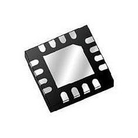
TGA2521-SM-T/R TriQuint, TGA2521-SM-T/R Datasheet - Page 4

TGA2521-SM-T/R
Manufacturer Part Number
TGA2521-SM-T/R
Description
RF Amplifier 17 - 24 GHz Driver
Manufacturer
TriQuint
Type
Linear Driver Amplifierr
Datasheet
1.TGA2521-SM-TR.pdf
(18 pages)
Specifications of TGA2521-SM-T/R
Mounting Style
SMD/SMT
Operating Frequency
17 GHz to 24 GHz
P1db
23.5 dBm
Noise Figure
5 dB
Operating Supply Voltage
5 V
Supply Current
320 mA
Maximum Power Dissipation
3.9 W
Package / Case
QFN-16
Lead Free Status / RoHS Status
Lead free / RoHS Compliant
Other names
1059496
1/
1/
2/
Maximum Power Dissipation
Thermal Resistance, θjc
Thermal Resistance, θjc
Mounting Temperature
Storage Temperature
Under RF Drive
For a median life of 1E+6 hours, Power Dissipation is limited to
For a median life of 1E+6 hours, Power Dissipation is limited to
Channel operating temperature will directly affect the device lifetime. For maximum life, it is
recommended that channel temperatures be maintained at the lowest possible levels.
Parameter
TriQuint Semiconductor: www. triquint.com (972)994-8465 Fax (972)994-8504 Info-mmw@tqs.com
Median Lifetime (Tm) vs. Channel Temperature
Pd(max) = (150 °C – Tbase °C)/θjc.
Power Dissipation and Thermal Properties
1.E+13
1.E+12
1.E+11
1.E+10
1.E+09
1.E+08
1.E+07
1.E+06
1.E+05
1.E+04
25
FET3
Tbaseplate = 85 ° C
Vd = 5 V
Id = 320 mA
Pd = 1.6 W
Vd = 5 V
Id = TBD mA
Pout = TBD dBm
Pd = TBD W
30 Seconds
50
Test Conditions
Channel Temperature ( C)
75
Table IV
Feb 2011 © Rev D
Feb 2010 © Rev C
100
125
150
Tchannel = TBD ° C
Tchannel = 200 ° C
Tchannel = 127 ° C
°
Tm = 7.7E+6 Hrs
θjc = 29.5 ° C/W
θjc = TBD ° C/W
Tm = TBD Hrs
-65 to 150 ° C
Pd = 3.9 W
Value
320 ° C
175
TGA2521-SM
200
Notes
1/ 2/
4


