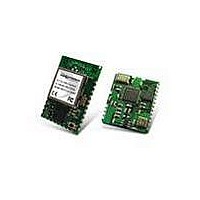
RK-WI.232DTS-FCC-R Radiotronix, RK-WI.232DTS-FCC-R Datasheet - Page 7

RK-WI.232DTS-FCC-R
Manufacturer Part Number
RK-WI.232DTS-FCC-R
Description
RF Modules & Development Tools Wi.232DTS-FCC-R RAPID DEV KIT
Manufacturer
Radiotronix
Datasheet
1.RK-WI.232DTS-FCC-R.pdf
(23 pages)
Specifications of RK-WI.232DTS-FCC-R
Lead Free Status / RoHS Status
Lead free / RoHS Compliant
Other names
RK-WI232DTS-FCC-R
WI.232DTS-FCC-R USER’S MANUAL
2. RApid Development Kit Setup
• Insert the AAA batteries into the evaluation PCB, observing the correct polarity.
• Insert an Wi.232DTS-FCC-R module into one of the evaluation boards, observing the correct
• Insert the other Wi.232DTS-FCC-R module into the other evaluation board, also observing the correct
• Connect antennas to Wi.232DTS-FCC-R modules.
• Connect evaluation boards to computers. If using USB communications, populate USB jumpers and
• Install the RK-Wi.232DTS-FCC-R Windows software. If already installed, skip this step.
• Run the RK-Wi.232DTS-FCC-R software, select 2400 baud operation and navigate to the “Wireless
• Power-On both evaluation boards, verifying that the version/copyright information is echoed to the
• Chat back and forth between evaluation boards, verifying that serial and RF communications are
•
orientation (see later in this document). The correct orientation of the module is with the antenna
connector closest to the edge of the evaluation board. Make sure it is seated fully and correctly.
polarity.
remove RS-232 jumpers. If using RS-232 communications, populate RS-232 jumpers and remove USB
jumpers.
Chat” tab.
screen from both modules.
successful.
IMPORTANT NOTE FOR HYPERTERMINAL
6
USERS: See section 4.1
Chapter
2


