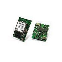
RK-WI.232DTS-FCC-R Radiotronix, RK-WI.232DTS-FCC-R Datasheet - Page 11

RK-WI.232DTS-FCC-R
Manufacturer Part Number
RK-WI.232DTS-FCC-R
Description
RF Modules & Development Tools Wi.232DTS-FCC-R RAPID DEV KIT
Manufacturer
Radiotronix
Datasheet
1.RK-WI.232DTS-FCC-R.pdf
(23 pages)
Specifications of RK-WI.232DTS-FCC-R
Lead Free Status / RoHS Status
Lead free / RoHS Compliant
Other names
RK-WI232DTS-FCC-R
WI.232DTS-FCC-R USER’S MANUAL
4. Using the Evaluation Software
4.1. Setting Register Values
4.2. Diagnostic Command Modes
4.3. Transceiver Mode
On both the Volatile and Non-Volatile pages, the registers are labeled by function. To set a register value,
select the value from the options available for that register and click the “Write” button. To perform a read of
that register, simply click the “Read” button. Descriptions of the register functions can be found in the
Wi.232DTS Users Manual.
There are a special class of commands available through the evaluation software. These controls are
located on the “Volatile Registers” page as seen below.
These commands place the module into special diagnostic modes that can be used to test the module’s
performance, or to activate the transmitter for RF testing purposes. It is important to note that once a module
executes a diagnostic command, it should be reset or have the power cycled to return to normal operation.
This selects the modulation mode and power output of both the transmitter and receiver. The mode is
not set until “Set TX Diag” or “Set RX Diag” is pressed. If “Set RX Diag” is pressed, the power output
value is ignored.
10
Chapter
4


