AVR-P40N-8535-8MHz Olimex Ltd., AVR-P40N-8535-8MHz Datasheet
AVR-P40N-8535-8MHz
Specifications of AVR-P40N-8535-8MHz


Related parts for AVR-P40N-8535-8MHz


AVR-P40N-8535-8MHz Summary of contents
Page 1
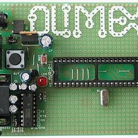
... AVR-P40-8535 development board All boards produced by Olimex are ROHS compliant Copyright(c) 2009, OLIMEX Ltd, All rights reserved Users Manual Revision A, October 2009 Page1 ...
Page 2
... INTRODUCTION The AVR Microcontroller are low-power CMOS 8-bit controller based on the RISC architecture. The AVR core combines a rich instruction set with general purpose working registers. All the registers are directly connected to the Arithmetic Logic Unit (ALU), allowing two independent registers to be accessed in one single instruction executed in one clock cycle ...
Page 3
... BOARD USE REQUIREMENTS Cables: The cable you will need depends on the programmer/debugger you use. If you use AVR-PG1, or AVR-JTAG-L, you will need RS232 cable, if you use PG2, you will need LPT cable, if you use AVR-ISP500, AVR-ISP500-TINY, ISP500-ISO, or Hardware: Programmer/Debugger – ...
Page 4
SCHEMATIC Page4 ...
Page 5
... AC max 9.0V AC. RESET CIRCUIT AVR-P40-8535 reset circuit includes pin 5 of ICSP connector, pin 6 of JTAG connector, pin 9 of U3, Reset scheme – U1 and RESET button (RST). CLOCK CIRCUIT Quartz crystal 8MHz is connected to AVR Microcontroller pin 12 (XTAL2) and pin 13 (XTAL1). Page5 ...
Page 6
JUMPER DESCRIPTION J1 When 1-2 are shorted – RTS is connected to terminal pin RTS/DTR. When 2-3 are shorted – DTR is connected to terminal pin RTS/DTR. Default state is 1-2. LED_J When this jumper is open – LED is ...
Page 7
... RI - Not connected Note1: RTS and DTR is connected to terminal pins via jumper J1, which position is describe bellow. Note2: RX RS232 driver pins have to be connected to AVR microcontroller pin - TXD/PD1 (PIN 15). TX RS232 driver pins have to be connected to AVR microcontroller pin - RXD/PD0 (PIN 14). PWR PIN # ...
Page 8
MECHANICAL DIMENSIONS Page8 ...
Page 9
... AVAILABLE DEMO SOFTWARE AVR-P40-8535 + ATmega16 blink LED AVR-P40-8535 + ATmega16 UART demo code HEX) AVR-P40-8535 + ATMega16 Button demo code HEX) AVR-P40-8535 + ATMega16 UART menu demo code and HEX) (C source Page9 and HEX) (C source and (C source and (C source ...
Page 10
... ORDER CODE AVR-P40-8535-8MHz completely assembled and tested with 8Mhz oscillator AVR-P40-8535/PCB ONLY How to order? You can order to us directly or by any of our distributors. Check our web Revision history REV.A www.olimex.com/dev for more info. - created October 2009 Page10 ...
Page 11
... However all warranties implied or expressed including but not limited to implied warranties of merchantability or fitness for purpose are excluded. This document is intended only to assist the reader in the use of the product. OLIMEX Ltd. shall not be liable for any loss or damage arising from the use of any information in this document or any error or omission in such information or any incorrect use of the product ...