AVR-P20B-10MHZ Olimex Ltd., AVR-P20B-10MHZ Datasheet
AVR-P20B-10MHZ
Manufacturer Part Number
AVR-P20B-10MHZ
Description
MCU, MPU & DSP Development Tools PROTOTYPE BRD FOR STK200 20PIN
Manufacturer
Olimex Ltd.
Specifications of AVR-P20B-10MHZ
Processor To Be Evaluated
AVR-PG1B, AVR-PG2B
Data Bus Width
8 bit
Interface Type
RS-232
Dimensions
100 mm x 80 mm
Operating Supply Voltage
3.3 V, 5 V
External Height
80mm
External Width
100mm
Mcu Supported Families
AVR
Rohs Compliant
Yes
Tool Type
Prototyping Board
Core Architecture
AVR
Cpu Core
AVR 8
Lead Free Status / RoHS Status
Lead free / RoHS Compliant
Other names
1776314 52R3437 AVR-P20-10MHZ


Features:
AVR-P20B is prototype board for 20 pin AVR
microcontrollers with following features:
Programming:
To program AVR-P20B you need serial port or
parallel port AVR-ICSP programmer dongle
(Olimex part # AVR-PG1B or AVR-PG2B).
The serial port ICSP programmer (AVR-PG1B)
works with PonyProg software by from Claudio
Lanconelli and the latest release may be
download for free from http://www.lancos.com
- RS232 Tx, Rx interface with MAX232 IC
- ICSP 10 pin connector (STK compatible)
- RESET IC ZM33064C
- Status
- 4MHz, 10MHz or 12MHz quartz oscillator
- extension slot on each microcontroller pin
- DIL20 microcontroller socket
- power supply plug in connector
- +5V power supply voltage regulator
- 0.1” (2.54 mm) grid
- dimensions: 100x80 mm
- four mounting holes
removable jumper
Development boards for PIC, AVR and MSP430 microcontrollers
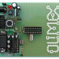
AVR-P20B PROTOTYPE BOARD WITH 10 PIN ICSP CONNECTOR
LED
connected
FOR 20 PIN AVR MICROCONTROLLERS
Copyright(c) 2002, OLIMEX Ltd, All rights reserved.
to
PB7
via
The parallel port ICSP programmer (AVR-
PG2B) works with AVR ISP from Atmel and
may be download for free from Atmel’s web site.
ICSP interface:
The ICSP connector is 2x5 pin with 0,1" step and
Atmel STKxxx compatible layout. The PIN.1 is
marked with square pad on bottom and arrow on
top. ICSP signals are: 1- MOSI, 2- VCC, 3- NC,
4- GND, 5- RST, 6- GND, 7- SCK, 8- GND, 9-
MISO, 10- GND
TOP view PCB board layout:
RS232 interface:
J1 removable jumper selects where RTS/DTR
line to be connected. In position 12 the line is
connected to RTS, in position 23 is connected to
DTR.
Status LED:
Connected to PB7 via removable jumper J2. The
jumper should be left open while programming.
Oscillator circuit:
Crystal resonator connected to XTAL1 and
XTAL2.
RESET supervisor circuit:
IC ZM33064C with 4.6V threshold.
Supported devices:
AT90S1200 and AT90S2313 microcontrollers.
Power supply:
The power supply should be in range +7.5
+18VDC.
Ordering codes:
AVR-P20B-4MHz
AVR-P20B-10MHz
AVR-P20B-12MHz
AVR-P20B/PCB
http://www.olimex.com/dev
- assembled and tested
- assembled and tested
- assembled and tested
- only PCB
Related parts for AVR-P20B-10MHZ
Image
Part Number
Description
Manufacturer
Datasheet
Request
R

Part Number:
Description:
MCU, MPU & DSP Development Tools ETHERNET CONTROLLER HEADER BRD 50x40mm
Manufacturer:
Olimex Ltd.
Datasheet:

Part Number:
Description:
MCU, MPU & DSP Development Tools DEV PROTOTYPE BRD FOR TMS470A256
Manufacturer:
Olimex Ltd.
Datasheet:

Part Number:
Description:
MCU, MPU & DSP Development Tools ETHERNET CONTROLLER HEADER BRD 53x29mm
Manufacturer:
Olimex Ltd.
Datasheet:

Part Number:
Description:
MCU, MPU & DSP Development Tools MP3 PLYR MOD WVS1002 W/VS1002
Manufacturer:
Olimex Ltd.
Datasheet:

Part Number:
Description:
MCU, MPU & DSP Development Tools PoE INJECTOR FOR PIC-MICRO-WEB
Manufacturer:
Olimex Ltd.

Part Number:
Description:
Development Boards & Kits - ARM OLINUXINO MICRO SBC ALLWINNER A10S CTXA8
Manufacturer:
Olimex Ltd.
Part Number:
Description:
Other Development Tools EKG / EMG SHIELD FOR DUINOMITE
Manufacturer:
Olimex Ltd.

Part Number:
Description:
MCU, MPU & DSP Development Tools DEV BRD FOR LPC2378 512KB FLASH 16KB RAM
Manufacturer:
Olimex Ltd.

Part Number:
Description:
MCU, MPU & DSP Development Tools HDR BRD FOR LPC2294 1MB SRAM 4MB FLASH
Manufacturer:
Olimex Ltd.

Part Number:
Description:
MCU, MPU & DSP Development Tools DEV BRD FOR LPC2919 768KB FLASH 56KBSRAM
Manufacturer:
Olimex Ltd.
Datasheet:

Part Number:
Description:
Microcontroller & Microprocessor Development Tools TCP-IP DEV BRD PIC32MX460F512
Manufacturer:
Olimex Ltd.
Datasheet:

Part Number:
Description:
Microcontroller & Microprocessor Development Tools PROTOTYPE BOARD TMS320F28027
Manufacturer:
Olimex Ltd.
Datasheet:

Part Number:
Description:
Microcontroller & Microprocessor Development Tools HDR BRD FOR LPC3131
Manufacturer:
Olimex Ltd.
Datasheet:

Part Number:
Description:
Microcontroller & Microprocessor Development Tools MP3 PLYR MOD WITH VS1002
Manufacturer:
Olimex Ltd.
Datasheet:
Part Number:
Description:
Microcontroller & Microprocessor Development Tools MP3 PLYR MOD BAT WITH VS1002
Manufacturer:
Olimex Ltd.
Datasheet:
AVR-P20B-10MHZ Summary of contents
Page 1
... RESET supervisor circuit: IC ZM33064C with 4.6V threshold. Supported devices: AT90S1200 and AT90S2313 microcontrollers. Power supply: The power supply should be in range +7.5 +18VDC. Ordering codes: AVR-P20B-4MHz AVR-P20B-10MHz AVR-P20B-12MHz AVR-P20B/PCB - assembled and tested - assembled and tested - assembled and tested - only PCB http://www.olimex.com/dev ...
Page 2
...