OM6274 NXP Semiconductors, OM6274 Datasheet - Page 5
OM6274
Manufacturer Part Number
OM6274
Description
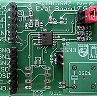
Interface Modules & Development Tools I2C to SPI Master Bridge Demoboard
Manufacturer
NXP Semiconductors
Datasheet
1.OM6274.pdf
(25 pages)
Specifications of OM6274
Interface Type
I2C, SPI
Data Bus Width
8 bit
For Use With/related Products
SC18IS602IPW
Lead Free Status / RoHS Status
Lead free / RoHS Compliant
Available stocks
Company
Part Number
Manufacturer
Quantity
Price
Company:

Part Number:
OM6274
Manufacturer:
NXP Semiconductors
Quantity:
135


NXP Semiconductors
SC18IS602_602B_603_4
Product data sheet
7.1.1 Addressing
7.1.2 Write to data buffer
7.1.3 SPI read and write - Function ID 01h to 0Fh
The first seven bits of the first byte sent after a START condition defines the slave address
of the device being accessed on the bus. The eighth bit determines the direction of the
message. A ‘0’ in the least significant position of the first byte means that the master will
write information to a selected slave. A ‘1’ in this position means that the master will read
information from the slave. When an address is sent, each device in a system compares
the first seven bits after the START condition with its address. If they match, the device
considers itself addressed by the master as a slave-receiver or slave-transmitter,
depending on the R/W bit.
A slave address of the SC18IS602/602B/603 is comprised of a fixed and a programmable
part. The programmable part of the slave address enables the maximum possible number
of such devices to be connected to the I
three programmable address bits (defined by the A2, A1, and A0 pins), it is possible to
have eight of these devices on the same bus.
The state of the A2, A1, and A0 pins are latched at reset. Changes made after reset will
not alter the address.
All communications to or from the SC18IS602/602B/603 occur through the data buffer.
The data buffer is 200 bytes deep. A message begins with the SC18IS60x address,
followed by the Function ID. Depending upon the Function ID, zero to 200 data bytes can
follow.
The SC18IS60x will place the data received into a buffer and continue loading the buffer
until a STOP condition is received. After the STOP condition is detected, further
communications will not be acknowledged until the function designated by the Function ID
has been completed.
Data in the buffer will be sent to the SPI port if the Function ID is 01h to 0Fh. The Function
ID contains the Slave Select (SS) to be used for the transmission on the SPI port. There
are four Slave Selects that can be used, with each SS being selected by one of the bits in
Fig 5.
Fig 6.
Slave address
Write to data buffer
S
SLAVE ADDRESS
Rev. 04 — 11 March 2008
0
W
1
A
fixed
slave address
0
FUNCTION ID
2
C-bus. Since the SC18IS602/602B/603 have
1
programmable
SC18IS602/602B/603
A2
A1
A0
002aac446
A
R/W
X
0 TO 200 BYTES
I
2
C-bus to SPI bridge
002aac447
© NXP B.V. 2008. All rights reserved.
A
P
5 of 25
Related parts for OM6274
Image
Part Number
Description
Manufacturer
Datasheet
Request
R

Part Number:
Description:
NXP Semiconductors designed the LPC2420/2460 microcontroller around a 16-bit/32-bitARM7TDMI-S CPU core with real-time debug interfaces that include both JTAG andembedded trace
Manufacturer:
NXP Semiconductors
Datasheet:

Part Number:
Description:
NXP Semiconductors designed the LPC2458 microcontroller around a 16-bit/32-bitARM7TDMI-S CPU core with real-time debug interfaces that include both JTAG andembedded trace
Manufacturer:
NXP Semiconductors
Datasheet:
Part Number:
Description:
NXP Semiconductors designed the LPC2468 microcontroller around a 16-bit/32-bitARM7TDMI-S CPU core with real-time debug interfaces that include both JTAG andembedded trace
Manufacturer:
NXP Semiconductors
Datasheet:
Part Number:
Description:
NXP Semiconductors designed the LPC2470 microcontroller, powered by theARM7TDMI-S core, to be a highly integrated microcontroller for a wide range ofapplications that require advanced communications and high quality graphic displays
Manufacturer:
NXP Semiconductors
Datasheet:
Part Number:
Description:
NXP Semiconductors designed the LPC2478 microcontroller, powered by theARM7TDMI-S core, to be a highly integrated microcontroller for a wide range ofapplications that require advanced communications and high quality graphic displays
Manufacturer:
NXP Semiconductors
Datasheet:
Part Number:
Description:
The Philips Semiconductors XA (eXtended Architecture) family of 16-bit single-chip microcontrollers is powerful enough to easily handle the requirements of high performance embedded applications, yet inexpensive enough to compete in the market for hi
Manufacturer:
NXP Semiconductors
Datasheet:
Part Number:
Description:
The XA-S3 device is a member of Philips Semiconductors? XA(eXtended Architecture) family of high performance 16-bitsingle-chip microcontrollers
Manufacturer:
NXP Semiconductors
Datasheet:

Part Number:
Description:
The NXP BlueStreak LH75401/LH75411 family consists of two low-cost 16/32-bit System-on-Chip (SoC) devices
Manufacturer:
NXP Semiconductors
Datasheet:
Part Number:
Description:
The NXP LPC3130/3131 combine an 180 MHz ARM926EJ-S CPU core, high-speed USB2
Manufacturer:
NXP Semiconductors
Datasheet:
Part Number:
Description:
The NXP LPC3141 combine a 270 MHz ARM926EJ-S CPU core, High-speed USB 2
Manufacturer:
NXP Semiconductors
Part Number:
Description:
The NXP LPC3143 combine a 270 MHz ARM926EJ-S CPU core, High-speed USB 2
Manufacturer:
NXP Semiconductors

Part Number:
Description:
The NXP LPC3152 combines an 180 MHz ARM926EJ-S CPU core, High-speed USB 2
Manufacturer:
NXP Semiconductors
Part Number:
Description:
The NXP LPC3154 combines an 180 MHz ARM926EJ-S CPU core, High-speed USB 2
Manufacturer:
NXP Semiconductors

Part Number:
Description:
Standard level N-channel enhancement mode Field-Effect Transistor (FET) in a plastic package using NXP High-Performance Automotive (HPA) TrenchMOS technology
Manufacturer:
NXP Semiconductors
Datasheet: