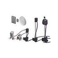
E39-L59 Omron, E39-L59 Datasheet - Page 10

E39-L59
Manufacturer Part Number
E39-L59
Description
Industrial Photoelectric Sensors VERT MTG BRACKT E3S
Manufacturer
Omron
Type
General Purpose Photoelectric Sensorr
Specifications of E39-L59
Features
Control the laser with an Amplifier the same size as a Digital Fiber Amplifier
Light Source
Infrared LED
Connection
Prewired Cable
Output Configuration
NPN
Accessory Type
Mounting Bracket(s)
For Use With
E3S-A Sensors
Lead Free Status / RoHS Status
Lead free / RoHS Compliant
For Use With/related Products
Vertical E3S-A Series
Lead Free Status / RoHS Status
Lead free / RoHS Compliant, Lead free / RoHS Compliant
Safety Precautions
This product is not designed or rated for
ensuring safety of persons.
Do not use it for such purposes.
Do not use the product in atmospheres or environments that
exceed product ratings.
Mounting
Position of Optical Axis of Through-beam Model
Unlike conventional through-beam sensors, the E3S-A
Through-beam Photoelectric Sensor incorporates 2 lenses.
The lens actually in use is the one marked with an arrow
indicating the position of the optical axis. When using a Slit,
attach it to the lens marked with the arrow.
Tightening the Connector
Manually tighten the connector until the threads have
completely disappeared. If tightening is insufficient, the
degree of protection may not be maintained, or the connector
may become loose when it is subjected to vibration. Using
pliers to tighten the connector may damage it.
Use the E39-L60 Close Mounting Plate (provided) if the
Sensor is mounted using mounting brackets or if it is mounted
directly. (Refer to Dimensions.)
Unused lens
Arrow indicating optical axis position
Lens actually in use (attach the Slit to this lens)
Screw
Precautions for Correct Use
Position of Arrow Indicating Optical Axis
http://www.ia.omron.com/
(Vertical Sensors)
(Horizontal
Optical axis indicator arrow
Sensors)
Model
E3S-A
E3S-A
WARNING
Position of lens in use
Bottom
Top
Mounting Bracket (Provided)
The direction of the optical axis coincides with the machine
axis of the E3S-A when the mounting screw is inserted into
the lock hole of the Mounting Bracket. If the mounting surface
and the screw hole are correctly aligned toward the sensing
object (or toward the Retroreflector for a Through-beam
Sensor), the mechanical axis and optical axis will be aligned
when the screw is inserted into the hole. Incident light will be
detected, and time-consuming adjustment will not be
necessary. (If, however, the mounting surface is not flat,
adjustment of the optical axis may still be required.)
Adjust the position of the Sensor so that incident light points
at the center. Make sure that the incident light is at a fixed
position.
The maximum tightening torque of the screw is 0.53 N.m max.
● Adjustments
E39-S46 Through-beam Slits
(Accessory, order separately)
Use the rubber attachment with the metal cover if a slit width
of 2 mm is required. (A Slit is not required in this case.) Insert
the 0.5- or 1-mm Slit between the metal cover and rubber
attachment if a slit width of 0.5 or 1 mm is desired.
These Slits fit into the rubber attachment.
Apply the Slit to the lens of the Photoelectric Sensor marked
with an arrow indicating the position of the optical axis (apply
it to the bottom lens of Horizontal Sensors and the top lens of
Vertical Sensors).
(c)Copyright OMRON Corporation 2008 All Rights Reserved.
13.6 mm
Optical axis
2 mm
Machine axis
11.1 mm
Indented portions
Metal cover
Slit (0.5 mm or 1 mm)
E3S-A
Optical axis lock hole (M3)
Rubber attachment
Bracket can move
in this direction
Base of mounting
bracket
Arrow indicating
position of optical axis
E3S-A
10


