E39-L59 Omron, E39-L59 Datasheet
E39-L59
Specifications of E39-L59


Related parts for E39-L59


E39-L59 Summary of contents
Page 1
Built-in Amplifier Photoelectric Sensor (Medium Size) E3S-A Be sure to read Safety Precautions on page 10. Ordering Information Built-in Amplifier Photoelectric Sensors Connection Sensing method Appearance method Pre-wired Horizontal Connector (M12) Through-beam Sensors *1 Pre-wired Vertical Connector (M12) Pre-wired Horizontal ...
Page 2
... Emitter/Receiver Can be used with the E3S-AT@@ Through-beam Sensor. ➜ (4 Filters total) Page 10 Model Quantity * E39- E39- E39- E39-RS1 1 * E39-RS2 1 * E39-RS3 1 E39-R5 1 E3S-A Model NPN output PNP output E3S-AD13 *3 E3S-AD33 E3S-AD23 E3S-AD43 Self Diagnosis E3S-AD11 E3S-AD31 Turbo E3S-AD21 E3S-AD41 ...
Page 3
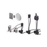
... Mounting Brackets/Other Appearance Model Quantity E39-L69 E39-L70 E39-L59 E39-L81 E39-L97 E39-L98 E39-L60 Note Through-beam Model is used, order two Mounting Brackets, one for the Emitter and one for the Receiver. Sensors I/O Connectors Model Quantity Remarks E39-G2 1 Provided with product. Sensors I/O Connectors ...
Page 4
... MSR function) E3S-AR11, 16, 21, 31, E3S-AD13, 18, 23, 33, 36, 41, 61, 66, 71, 81, 38, 43, 63, 68, 73, 83, 86, 91 88, 93 100 mm (wide view (100 mm) *1 (white paper 100 × (When using E39-R1) 100 mm) Opaque: 75-mm dia. min. 20% max. of sensing --- distance 3 to 10° Infrared LED (880 nm max. (plus approx ...
Page 5
... E3S-AD@1/@ 400 600 800 Distance X (m) 200 −10 E3S-AD@2/@7 −20 −30 E3S-AD@3/@8 −40 Retro-reflective Sensors E3S-AR@@ + E39-R1 (with Reflector) 100 E39-R1 Reflector Oper- ating 1 level 0 0.2 0.4 0.6 0.8 1 1.2 1.4 1.6 1.8 2 2.2 2.4 2.6 Distance (m) E3S-A Through-beam Sensors E3S-AT@@ + E39-E6 ...
Page 6
Diffuse-reflective Sensor E3S-AD@1/AD@2/AD@3/AD@6/AD@7/ AD@8 (Detection of White Paper) 500 Sensing object: White paper 300 E3S- 100 × 100 mm E3S- 200 × 200 mm 100 50 30 E3S-AD@2/@7 ...
Page 7
Operation Model Timing charts mode Incident light No incident light ON Light indicator (red) OFF Light-ON ON Output transistor OFF Operate Load (e.g., relay) Reset (Between brown and black) T: OFF-delay timer (0 to 100 ms) Incident light E3S-AT21 * ...
Page 8
PNP Output Operation Model Timing charts mode E3S-AT31 * Incident light No incident light E3S-AT36 * ON Light indicator E3S-AT81 * (red) OFF E3S-AT86 * Light-ON ON Output transistor OFF Operate E3S-AR31 Load (e.g., relay) Reset E3S-AR36 E3S-AR81 Incident light ...
Page 9
Operation Model Timing charts mode Incident light No incident light ON Light indicator (red) OFF Light-ON ON Output transistor OFF Operate Load (e.g., relay) Reset E3S-AR41 T: OFF-delay timer (0 to 100 ms) E3S-AR91 Incident light No incident light ON ...
Page 10
... Using pliers to tighten the connector may damage it. Screw Use the E39-L60 Close Mounting Plate (provided) if the Sensor is mounted using mounting brackets mounted directly. (Refer to Dimensions.) Mounting Bracket (Provided) ...
Page 11
... N max. Sensitivity adjuster The OFF-delay timer adjuster is used as a turbo switch (black). Using the E39-R5 Optical Axis Reflector for Through- beam Sensors (Accessory, order Separately) Use this attachment when the set distance is long and adjustment is mechanically difficult with a sensing object ...
Page 12
Dimensions E3S-A Built-in Amplifier Photoelectric Sensor Through-beam Sensors (Horizontal) Pre-wired Sensors E3S-AT11/21/31/41 (Receiver) With Mounting Bracket Attached Optical axis 28.9 16.9 Emitter: E3S-AT@@-L Receiver: E3S-AT@@-D 5 10.5 Optical axis 29.2 5.5 1.2 10.7 A* *The Mounting Bracket can be attached ...
Page 13
Sensors with Standard Connectors E3S-AT16/36 (Receiver) With Mounting Bracket Attached Optical axis 16.9 28.9 5 10.5 Optical axis 29.2 5.5 1.2 10.7 A* *The Mounting Bracket can be attached to side A. E3S-AT16/36 (Emitter) With Mounting Bracket Attached Optical axis ...
Page 14
Through-beam Sensors (Vertical) Pre-wired Sensors E3S-AT61/71/81/91 (Receiver) With Mounting Bracket Attached Optical axis Optical axis 16.9 28.9 5.5 5.4 29.2 1.2 10.7 A* 10.5 *The Mounting Bracket can be attached to side A. E3S-AT61/81 (Emitter) With Mounting Bracket Attached Optical ...
Page 15
... A* 10.5 E39-L60 Close Mounting Plate (provided) (Attach the mounting plate or the plug cannot be connected.) *The Mounting Bracket can be attached to side A. Note: Models numbers for Through-beam Sensors (E3S-AT@6) are for sets that include both the Emitter and Receiver. ...
Page 16
Retro-reflective Sensors (Horizontal) Pre-wired Sensors E3S-AR11/21/31/41 With Mounting Bracket Attached Optical axis 28.9 16.9 5 10.5 Optical axis 9 29.2 1.2 10.7 A* *The Mounting Bracket can be attached to side A. Sensors with Connectors E3S-AR16/36 With Mounting Bracket Attached ...
Page 17
... Optical axis 31.4 19.4 Stainless steel (SUS304) 31.5 1.2 10.7 A* 10.5 E39-L60 Close Mounting Plate (provided) (Attach the mounting plate or the plug cannot be connected.) *The Mounting Bracket can be attached to side A. Lens (5.7 × 10.9) 4.8 Stainless steel (SUS304) Light indicator 3.1 ...
Page 18
Diffuse-reflective Sensors (Horizontal) Pre-wired Sensors E3S-AD11/12/13/21/22/23 -AD31/32/33/41/42/43 With Mounting Bracket Attached Optical axis 28.9 16.9 5 10.5 Optical axis 29.2 9 1.2 10.7 A* *The Mounting Bracket can be attached to side A. Sensors with Connectors E3S-AD16/17/18/36/37/38 With Mounting Bracket ...
Page 19
... Optical axis Optical axis 19.4 31.4 Stainless steel (SUS304) 29.2 1.2 10.7 A* 10.5 E39-L60 Close Mounting Plate (provided) (Attach the mounting plate or the plug cannot be connected.) *The Mounting Bracket can be attached to side A. 4.8 Stainless Stability indicator Light indicator (red) steel (green) (SUS304) 3 ...
Page 20
... Reflector: Acryl Back: ABS 40.9 In the interest of product improvement, specifications are subject to change without notice. Filters for Mutual Interference Prevention (For Through-beam Model) 6.8 11.6 E39-E6 A 2.1 Material: Stainless steel (SUS304) Quantity * Two of each for the Emitter and Receiver (total of four) Reflectors Mounting Brackets 15 ...
Page 21
... Please read and understand this catalog before purchasing the products. Please consult your OMRON representative if you have any questions or comments. WARRANTY OMRON's exclusive warranty is that the products are free from defects in materials and workmanship for a period of one year (or other period if specified) from date of sale by OMRON. OMRON MAKES NO WARRANTY OR REPRESENTATION, EXPRESS OR IMPLIED, REGARDING NON-INFRINGEMENT, MERCHANTABILITY, OR FITNESS FOR PARTICULAR PURPOSE OF THE PRODUCTS ...