HFBR-2526ETZ Avago Technologies US Inc., HFBR-2526ETZ Datasheet - Page 6
HFBR-2526ETZ
Manufacturer Part Number
HFBR-2526ETZ
Description
Fiber Optic Transmitters, Receivers, Transceivers Versatile Link Horiz
Manufacturer
Avago Technologies US Inc.
Series
Versatile Linkr
Specifications of HFBR-2526ETZ
Maximum Forward Current
80 mA
Maximum Power Dissipation
40 mW
Operating Voltage
7 V
Transmission Distance
43 m
Product
Receiver
Data Rate
155 MBd
Wavelength
660 nm
Diode Capacitance
86 pF
Maximum Rise Time
20 ns
Maximum Fall Time
20 ns
Pulse Width Distortion
40 ns
Maximum Output Current
250 uA
Operating Supply Voltage
7 V
Maximum Operating Temperature
+ 85 C
Minimum Operating Temperature
- 40 C
Data Transmission Distance
100m
Output Current Range
25mA
Wavelength Typ
650nm
Leaded Process Compatible
Yes
Peak Reflow Compatible (260 C)
Yes
Rohs Compliant
Yes
Voltage - Supply
4.75 V ~ 5.25 V
Power - Minimum Receivable
-21.6dBm
Current - Supply
6.2mA
Applications
General Purpose
Lead Free Status / RoHS Status
Lead free / RoHS Compliant


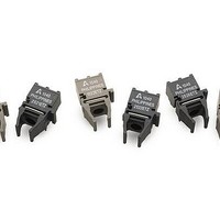
125 Megabaud Versatile Link Transmitter
HFBR-1527ETZ Series
Description
The HFBR-1527ETZ transmitters incorporate a 650 nano-
meter LED in a horizontal (HFBR-1527ETZ) gray housing.
The HFBR-1527ETZ transmitters are suitable for use with
current peaking to decrease response time and can be
used with HFBR-2526ETZ receivers in data links operating
at signal rates from 1 to 125 megabaud over 1 mm
diameter plastic optical fiber or 200 Pm diameter hard
clad silica glass optical fiber.
Absolute Maximum Ratings
6
Parameter
Storage Temperature
Operating Temperature
Lead Soldering Temperature Cycle Time
Transmitter High Level Forward Input Current
Transmitter Average Forward Input Current
Reverse Input Voltage
WARNING: when viewed under some conditions, the optical port may expose the eye beyond the maximum permissible
exposure recommended in ansi z136.2, 1993. Under most viewing conditions there is no eye hazard.
CAUTION: The small junction sizes inherent to the design of this component increase the component’s suscep ti bility
to damage from electrostatic discharge (ESD). It is advised that normal static precautions be taken in handling and
assembly of this component to prevent damage and/or degradation which may be induced by ESD.
Symbol
T
T
I
I
V
F,H
F,AV
O
S
R
CATHODE
GROUND
GROUND
ANODE
Min.
-40
-40
1
2
3
4
SEE NOTE 6
Max.
85
85
260
10
120
60
3
GROUND
GROUND
Unit
°C
°C
°C
s
mA
mA
V
Reference
Note 1, 9
50% Duty Cycle
≥ 1 MHz
Related parts for HFBR-2526ETZ
Image
Part Number
Description
Manufacturer
Datasheet
Request
R

Part Number:
Description:
RECEIVER FIBER OPTIC 600NM 5MBD
Manufacturer:
Avago Technologies US Inc.
Datasheet:

Part Number:
Description:
RECEIVER FIBER OPTIC 5MBD TTL ST
Manufacturer:
Avago Technologies US Inc.
Datasheet:

Part Number:
Description:
RCVR FIBER OPTIC INTERBUS-S
Manufacturer:
Avago Technologies US Inc.
Datasheet:

Part Number:
Description:
RCVR OPT HI PERF VERS LINK HORZ
Manufacturer:
Avago Technologies US Inc.
Datasheet:
Part Number:
Description:
RCVR OPT HI PERF VERS LINK HORZ
Manufacturer:
Avago Technologies US Inc.
Datasheet:

Part Number:
Description:
RECEIVER FIBER OPTIC 600NM 1MBD
Manufacturer:
Avago Technologies US Inc.
Datasheet:

Part Number:
Description:
RECEIVER FIBER OPTIC 600NM 1MBD
Manufacturer:
Avago Technologies US Inc.
Datasheet:

Part Number:
Description:
RECEIVER FIBER OPTIC VERT 1MBD
Manufacturer:
Avago Technologies US Inc.
Datasheet:

Part Number:
Description:
RECEIVER FIBER OPTIC 5MBD TTL ST
Manufacturer:
Avago Technologies US Inc.
Datasheet:

Part Number:
Description:
RECEIVER FIBER OPT 125MHZ ANA ST
Manufacturer:
Avago Technologies US Inc.
Datasheet:

Part Number:
Description:
OPTOCOUPLER GATE DRV 2A 16-SOIC
Manufacturer:
Avago Technologies US Inc.
Datasheet:
Part Number:
Description:
OPTOCOUPLER 2CH 2.5A 16-SOIC
Manufacturer:
Avago Technologies US Inc.
Datasheet:

Part Number:
Description:
OPTOCOUPLER GATE DRV 0.4A 16SOIC
Manufacturer:
Avago Technologies US Inc.
Datasheet:

Part Number:
Description:
OPTOCOUPLER 2.0A 250KHZ 8-DIP
Manufacturer:
Avago Technologies US Inc.
Datasheet:

Part Number:
Description:
OPTOCOUPLER 2.0A 250KHZ GW 8-SMD
Manufacturer:
Avago Technologies US Inc.
Datasheet: